
International IC Bus 3000-Series Workshop Repair Service Manual with Wiring Diagrams PDF - MINT3000BUS.zip
Full-service repair documentation, complete with electrical wiring diagrams, covering the International IC Bus 3000-Series — everything you need to service, troubleshoot, fix, and rebuild these vehicles the way professional technicians do.
Inside the IC Bus 3000-Series workshop service repair manual you'll find:
* Numbered table of contents easy to use so that you can find the information you need fast.
* Detailed sub-steps expand on repair procedure information
* Numbered instructions guide you through every repair procedure step by step.
* Troubleshooting and electrical service procedures are combined with detailed wiring diagrams for ease of use.
* Notes, cautions and warnings throughout each chapter pinpoint critical information.
* Bold figure number help you quickly match illustrations with instructions.
* Detailed illustrations, drawings and photos guide you through every procedure.
* Enlarged inset helps you identify and examine parts in detail.
0000975235 - 2017-2020 IC Bus CE Series Technician Manual (Service and Diagnostics), Revision 9.pdf
97H00601205 - MWM DIAGNOSTICS MANUAL ACTEON SERIES 4.12 AND 6.12 TCE Engines Service Manual.pdf
0001027267 - 2017-2020 IC Bus RE Series Technician Manual (Service and Diagnostics), Revision 6.pdf
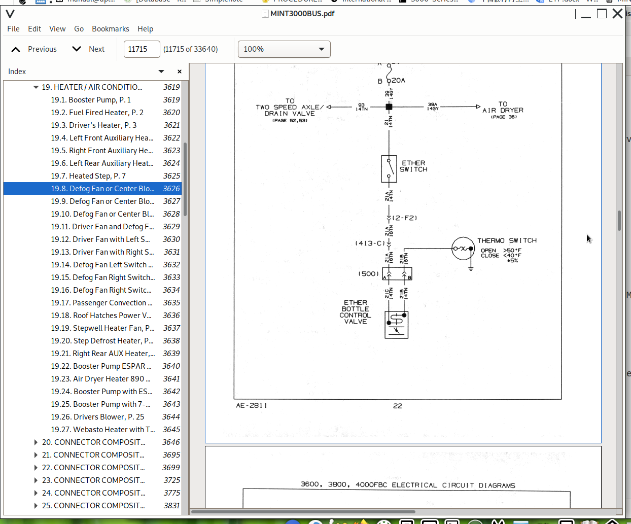
CTS-5123V - 3600, 3800, 4000FBC Chassis (Built November 1997 through February 1999) Electrical Circuit Diagrams.pdf
S13008 - 6 Speed Transmissions Eaton Series FS-5106 and FS-6206 Supersedes CTS-5179 (June 1996) Service Manual.pdf
0000020182 - 2016 - 2019 IC Bus BE _ CE Series Electrical Circuit Diagrams.pdf
0000002601 - 3200, RXT, DuraStar, TranStar, TranStar Natural Gas, WorkStar Series (Built May, 2010-) Electrical Circuit Diagrams (Supersedes S08343).pdf
S082503 - 3200 (Oct 2000 to May 2003) Electrical Troubleshooting Manual.pdf
S08291 - BE 200, CE Bus, CE 200 and CE 300 Series Built March, 2004 Electrical Circuit Diagrams.pdf
0000019443 - IC Bus RE Series (Built September 2017 and After) Body Electrical Circuit Diagrams.pdf
0000002843 - IC Bus RE Series Built November 2011 and After Body Electrical Circuit Diagrams.pdf
S05015Y - Power Steering Gear_ Sheppard M-Series, Supersedes CTS-5262 (Sept 2000) Service Manual.pdf
0000003601 - 2011 - 2015 IC Bus BE _ CE Series Electrical Circuit Diagrams (Supersedes S08377).pdf
S08290 - BE 200, CE 200, CE 300 Model Electrical System Troubleshooting Guide Service Manual.pdf
S47001Y - IC BUS Service Manual.pdf
S08335 - RE Bus Models Built 1999 to 2006 Body Electrical Circuit Diagrams.pdf
S082504 - 3200 (May 2003 to Feb 2007) Electrical Troubleshooting Manual.pdf
0000003361 - IC Bus BE _ CE Models Radiator _ Cooling System Service Manual.pdf
S082503A - Electrical System Troubleshooting Guide Models Built After 05_20_2003 (Apr 2004).pdf
S082504 - Electrical System Troubleshooting Guide Models Built 05_20_2003 to 02_28_2007 (Jan 2008).pdf
S082503 - Electrical System Troubleshooting Guide Models Built 10_16_2000 to 05_20_2003 (Jan 2008) Service Manual.pdf
0000002601 - 3200, RXT, DuraStar - 4100, 4300, 4400, TranStar Natural Gas (NG), TranStar - 8500, 8600, WorkStar - 7300, 7400, 7500, 7600, 7700 Electrical Circuit Diagram Manual.pdf
S05003Y - Power Steering Gear_ TRW _ ROSS-TAS 40, 55, 65 and 85, Supersedes CTS-5215 (Sept 2000) Service Manual.pdf
S08286 - IC Bus Models Built March 1, 2000 and After (Body) Electrical Circuit Diagrams.pdf
S08322 - 3200 (March 2007 to March 2008) Wiring Diagrams.pdf
0000017581 - 3600, 3800, 4000FBC Chassis Built November 1997 through February 1999 Electrical Circuit Diagrams.pdf
S08322 - 3200, 4100, 4200, 4300, 4400, 7300, 7400, 7500, 8500, 8600, RXT Models Built March 1, 2007 to March 18, 2008 Electrical Circuit Diagrams.pdf
0000002484 - BE, CE, CE Propane Autogas, HC and RE Buses Exhaust Aftertreatment System with DPF (Supersedes S07006) Service Manual.pdf
0000019442 - IC Bus RE Series (Built September 2017 and After) Chassis Electrical Circuit Diagrams.pdf
S08315 - 3200, 4100, 4200, 4300, 4400, 7300, 7400, 7500, 7600, 7700, 8500, 8600, MXT, RXT Models Built Oct. 1, 2005 to Feb. 28, 2007 Electrical Circuit Diagrams.pdf
0000002242 - IC Bus AE Series Electrical Circuit Diagrams.pdf
S10024 - Eaton Hybrid System Service Manual (Oct 2009).pdf
S47006 - BE 200 BUS FRONT END AND BODY COMPONENTS Service Manual.pdf
S14014 - SINGLE REDUCTION, SINGLE SPEED AXLES_ SPICER D135-S, F155-S, F170-S SERIES (Supersedes CTS-5233) Service Manual.pdf
S08298 - 3300 Model Electrical System Troubleshooting Guide (Jan 2008) Service Manual.pdf
S10028 - IC Bus CE Bus Eaton Hybrid System Service Manual (May 2011) Service Manual.pdf
S47009 - IC Bus AE Model Body ComponentsService Manual.pdf
S08320 - BE, CE Series Built August, 2006 Through February, 2007 (Chassis Only) Electrical Circuit Diagrams.pdf
S13010 - 5 Speed Transmissions Spicer ES62-5A, ES62-5D, ES67-5A and ES67-5D Supersedes CTS-5182 (June 1996) Service Manual.pdf
S08300 - 3300 Model Built March, 2004 to December, 2006 Electrical Circuit Diagrams (Jan 2007) Service Manual.pdf
0000002842 - 3200, DuraStar, TranStar, WorkStar, and RXT Models Built March, 2008 to May 16, 2010 Electrical Circuit Diagrams (Supersedes S08337).pdf
S08299 - 3300 Model Built March, 2004 to December, 2006 Electrical Circuit Diagrams (Jan 2007).pdf
S08266 - IC Bus Electrical System Troubleshooting Guide Built 03_01_2000 (Aug 2000) Service Manual.pdf
S082854 - 3200 (2004 to 2005) Wiring Diagrams.pdf
S47003 - FE 300 BUS BODY COMPONENTSService Manual.pdf
S14008T - SINGLE SPEED REAR AXLE_ INTERNATIONAL (Supersedes CTS-5108T) Service Manual.pdf
S082853 - 3200 (Sep 2003) Wiring Diagrams.pdf
0000019822 - FE and SFC Bus Series Euro III & V Circuit Diagram ManualCircuit Diagrams.pdf
S082853 - 3200, 4200, 4300, 4400, 7300, 7400, 7500, 7600, 8500, 8600 Models Built September 16, 2003 to March 10, 2004 Electrical Circuit Diagrams.pdf
S47005 - RE 200, RE 300 BUS BODY COMPONENTS Service Manual.pdf
S08337 - 3200 (March 2008 to March 2010) Wiring Diagrams.pdf
S13006H - 6 Speed Transmissions International Model ES52-7A and ESO65-7A 6-Plus Service Manual.pdf
S47004 - CE 200 AND CE 300 BUS BODY COMPONENTS Service Manual.pdf
S08351 - RE Bus Series Built January 2010 to June 2011 Body Electrical Circuit Diagrams.pdf
S08226XA - 3400, 3800, 4000 FBC Chassis Electrical Circuit Diagram Built October 1, 1999 and After, Supersedes CTS-5123X (April 1999).pdf
S08296 - FE 300, RE 200, RE 300 Build Date 03_01_2004 Electrical System Troubleshooting Guide (Feb 2007).pdf
S13009 - 5 Speed Transmissions Spicer ES43-5 and ES53-5 Supersedes CTS-5181 (March 1996) Service Manual.pdf
S16034 - HEAT VENTILATION AIR CONDITIONING (HVAC), TXV System, March 2007 - 2009 3200, 4100, 4200, 4300, 4400, 7300, 7400, 7500, 7600, 7700, 8500, 8600 Models, CXT, DuraStar, TranStar, WorkStar and RXT.pdf
0000002842 - 3200 (2008 to 2010) Wiring Diagrams.pdf
S13012 - 5 Speed Transmissions Spicer ES60-5 Supersedes CTS-5184 (March 1996) Service Manual.pdf
S16046 - 3200 Bus, DuraStar, TerraStar, TranStar, WorkStar Models Heat Ventilation Air Conditioning (HVAC) for 2010 Service Manual.pdf
S16046 - 2010 HVAC Service Manual.pdf
S09009 - Hood, Grille, Fenders and Bumper - CE 200, CE 300 (March 2004) Service Manual.pdf
S08340 - RE Bus Models Built January 2007 and After Body Electrical Circuit Diagrams.pdf
S11003 - Spicer 14-Inch (355.6 mm) Stamped Angle-Spring Clutch Supersedes CTS-5140 (March 1996) Service Manual.pdf
S16025 - HEAT VENTILATION AIR CONDITIONING (HVAC), Orifice Tube System, Pre-March 2007 - 3200, 4100, 4200, 4300, 4400, 7300, 7400, 7500, 7600, 7700, 8500, 8600 Service Manual.pdf
S16025 - 2005 HVAC Manual.pdf
S13011 - 5 Speed Transmissions Spicer ES70-5 Supersedes CTS-5183 (March 1996) Service Manual.pdf
S08324 - 3200, 4100, 4200, 4300, 4400, 7300, 7400, 7500, 7600, 7700, 8500, 8600, CXT, DuraStar, RXT, TranStar, and WorkStar Models Built After March 01, 2007 Electrical System Troubleshooting Guide Diagnostic Trouble Codes.pdf
S082852A - 3200, 4200, 4300, 4400, 7300, 7400, 7500, 7600, 8500, 8600 Models Built October 1, 2002 to September 15, 2003 Electrical Circuit Diagrams (Oct 2002).pdf
S08269 - 3000FE, 3000RE Electrical System Troubleshooting Guide Built Date 11_17_1997 Supersedes CTS-5282 (Jan 2000).pdf
S12023 - RE Bus Side Mount Cooling Package (Aug 2012) Service Manual.pdf
S09010 - Hood, Grille, Fenders and Bumper - 3300 (March 2004) Service Manual.pdf
S10018 - 3200 Integrated Mobility (IM) Option Service Manual (Oct 2005).pdf
S08003 - Allison WT Transmission Electronic Controls, Supersedes CTS-5090 (June 1996) Service Manual.pdf
0000650450 - IC Bus™ Propane Autogas CE Series Radiator _ Cooling SystemService Manual.pdf
S04038 - EC-17 Antilock Traction Controller, Supersedes CTS-5292 (Aug 1998) Service Manual.pdf
0000002841 - IC Bus RE Series Built November 2011 and After Body Electrical Circuit Diagrams.pdf
S04048 - Full Power Hydraulic ABS Brake System (Jan 2007)Service Manual.pdf
S04051 - Full Power Hydraulic ABS Brake System (Dec 2006) Service Manual.pdf
S11004 - Spicer 14 Inch (350 mm) Solo Clutch Supersedes CTS-5256 (March 1996) Service Manual.pdf
S04050 - Full Power Hydraulic ABS Brake System (Dec 2006)Service Manual.pdf
S09019 - IC Bus AC _ AE Model Hood, Grille, Fenders, and Bumper (2012) Service Manual.pdf
S12039 - IC Bus AC Model Radiator _ Cooling System (June 2012) Service Manual.pdf
0000944045 - SFC Bus™ Series Stripped Chassis ISB EPA04 Only Electrical Circuit Diagrams.pdf
ITEC DCU MWM SCR Post-Treatment Wiring Diagram Acteon Series 4.12 AND 6.12 TCE Euro VEngine Diagnostic Forms.pdf
S11015 - 3000 RE _ 3100 Midi Bus Hydraulic Clutch Service Manual (Feb 2010) Service Manual.pdf
S04024 - Antilock Air Brake System_ Bendix, Supersedes CTS-5114 (April 1996) Service Manual.pdf
S04025 - Antilock Air Brake System_ Bendix, Supersedes CTS-5115 (June 1996) Service Manual.pdf
S08364 - BE, CE Hybrid Bus Models Built November, 2010 Electrical Circuit DiagramsCircuit Diagrams.pdf
S16003 - Repair Instructions for Fiberglass and Plastic (ABS) Material (Formerly CTS-5173) Service Manual.pdf
S08334 - RE Bus Models Built July 01, 2007 and After Electrical Circuit Diagrams.pdf
ITEC ECU MWM Wiring Diagram Acteon Series 4.12 and 6.12 TCE Euro VEngine Diagnostic Forms.pdf
S040393 - Lucas Varity _ TRW Hydraulic Antilock Brake System (Dec 2003) Service Manual.pdf
S08345 - RE Bus Models Built August 16, 2010 and After Electrical Circuit Diagrams.pdf
S14015 - 2 SPEED REAR AXLES_ SPICER (Supersedes CTS-5193) Service Manual.pdf
S04016K - Caliper Disc Brakes, Supersedes CTS-5009K (March 1996) Service Manual.pdf
S07003 - Exhaust Aftertreatment and Diesel Particulate Filter (DPF) (Oct 2009) Aftertreatment.pdf
S04045 - Meritor _ WABCO Hydraulic ABS for Medium-Duty Trucks, Buses and Motor Home Chassis (June 2000) Service Manual.pdf
S12059 - FE Bus _ 3100 Bus Radiator_Cooling System Service Manual (Brazilian Market) (Aug 2012) Service Manual.pdf
S08314 - RE 200 and RE 300 Instruments (Data Link Driven Instrument Cluster) Service Manual.pdf
S08313 - IC Bus and FE 300 Bus Instruments (Data Link Driven Instrument Cluster) Service Manual.pdf
S08155X - Instruments (New Data Link Driven Instrument Cluster), Supersedes CTS-5228 (Oct 1999) Service Manual.pdf
S04007 - Reconditioning Brake Drums and Shoes, Supersedes CTS-5085 (March 1996) Service Manual.pdf
S05028 - 3100 Bus _ FE Bus Steering Column Assembly Brazilian Market (Aug 2012) Service Manual.pdf
S08154X - Speedometer _ Tachometer Diagnostics and Service, Supersedes CTS-5257 (Oct 1999) Service Manual.pdf
S03019 - Primaax Rear Air Suspension (2012) Service Manual.pdf
S04003R - Air Compressor_ Bendix TU-Flo 550 and TU-Flo 750, Supersedes CTS-5056R (March 1996) Service Manual.pdf
S04005 - Cam Air Foundation Brakes, Supersedes CTS-5060 (March 1996) Service Manual.pdf
S08034X - Instruments, Supersedes CTS-5088K (Oct 1999) Service Manual.pdf
S04004 - Air Compressor_ Bendix 2150, Supersedes CTS-5058 (March 1996) Service Manual.pdf
S03001K - Air Suspension with Tapered Leaf Springs, Supersedes CTS-5025K (March 1996) Service ManualM.pdf
S05006W - Power Steering Pump_ Eaton Model BB135 R, L, Supersedes CTS-5160 (Jan 1998) Service Manual.pdf
S03017 - Parasteer™ Front Air Suspension (2012) Service Manual.pdf
S12008 - Radiator, Removal and Replacement (2012) Service Manual.pdf
S04018W - Reconditioning Rotors, Supersedes CTS-5086W (June 1998) Service Manual.pdf
S04029 - Antilock Brakes_Traction Control_ Bendix - Principles, Operation and Service, Supersedes CTS-5246 (March 1996) Service Manual.pdf
S04011 - Air Compressor_ Midland Models EL-1300 and EL-1600, Supersedes CTS-5146 (March 1996) Service Manual.pdf
s04010 - Air Compressor_ Bendix TU-FLO 501, Supersedes CTS-5145 (March 1996) Service Manual.pdf
S07004 - Exhaust Aftertreatment and Diesel Particulate Filter (DPF) (Oct 2009).pdf
S03016 - Stabil-Ride™ Suspension (2010) Service Manual.pdf
S07009 - Exhaust Aftertreatment System and Diesel Particulate Filter (2012) Service Manual.pdf
S04020X - Double Diaphragm MGM Spring Brake, Supersedes CTS-5107X (Sept 1998) Service Manual.pdf
S11007R - Clutch Control Linkage Supersedes CTS-5061R (March 1996) Service Manual.pdf
S04017Y - Hydro-Max Brake Booster and Master Cylinder, Supersedes CTS-5018K (Dec 2000) Service Manual.pdf
S05013 - Steering Column Assembly, Standard and Tilt, Supersedes CTS-5168 (April 1996) Service Manualpdf
S08036 - Starting Motors (Delco-Remy), Supersedes CTS-5054 (March 1996) Service Manual.pdf
S03009 - MOR _ RYDE Rubber Spring Suspension, Supersedes CTS-5177 (March 1996) Service Manual.pdf
S03013 - International Ride Optimized Suspension (Dec 2005) Service Manual.pdf
S08327 - 2007 - 2010 Body Controller (BC) Diagnostic Trouble Codes Manual.pdf
S11002 - Spicer 13-Inch (310 mm) and 14-Inch (350 mm) Angle-Ring Single Plate Push-Type Clutch Supersedes CTS-5057 Service Manual.pdf
S04044 - Bosch Parking Brake_ Manual or Power Brake (Oct 2008) Service Manual.pdf
s12005 - Radiator Shutters, Supersedes CTS-5084 (March 1996)Service Manual.pdf
S05009T - Steering Column Assembly, Tilt_Telescoping, Supersedes CTS-5072T (Feb 1997) Service Manual.pdf
S05016 - Steering Wheel Removal and Installation (Sept 2010) Service Manual.pdf
S08328 - CE Bus Series Advanced Energy Hybrid Starting March, 2007 Electrical Circuit Diagrams.pdf
S05008T - Steering Column Assembly, Tilt, Supersedes CTS-5049T (Feb 1997) Service Manual.pdf
s08287 - 3000FE, 3000RE Electrical System Troubleshooting Guide Built Date 11_17_1997 Supersedes CTS-5282 (Jan 2000) Service Manual.pdf
S08312 - Aware Vehicle Intelligence System Diagnostic Trouble Codes (June 2005) Diagnostic Trouble Codes.pdf
S04006 - Rockwell Automatic Slack Adjusters (Oct 2006)Service Manual.pdf
PRODUCT DETAILS:
Total Pages: 33,640 pages
File Format: PDF (Internal Links, Bookmarked, Table of Contents, Searchable, Printable, high quality)
Language: English
MAIN SECTIONS
0000002242 - IC Bus AE Series Electrical Circuit Diagrams...1
0000002484 - BE, CE, CE Propane Autogas, HC and RE Buses Exhaust Aftertreatment System with DPF (Supersedes S07006) Service Manual...411
toc...413
Summary of Changes...413
1. Description...417
1.1. Theory of Operation...424
MaxxForce® DT...424
MaxxForce® 7...424
Cummins® ISB6.7...424
PSI 8.8 LPG Engine...424
1.2. Single Horizontal / Horizontal...425
2. General Service Information...426
2.1. Exhaust Aftertreatment System Modifications...427
2.2. Diesel Particulate Filter (DPF) Cleaning...428
Diesel Particulate Filter (DPF) and Diesel Oxidation Catalyst (DOC) Inspection...428
2.3. Gaskets And Fasteners...428
2.4. Diesel Particulate Filter (DPF) Indexing...429
2.5. Decomposition Reactor Tube Cleaning...429
2.6. Diesel Exhaust Fluid (DEF) Dosing Valve Cleaning...430
2.7. Diesel Exhaust Fluid (DEF) Tank Draining...431
3. Component Replacement...433
3.1. MaxxForce® 7 OR DT Systems...433
Pressure Tubes and Pressure Sensor – Removal...433
Pressure Tubes and Pressure Sensor – Installation...434
Temperature Sensor – Removal...435
Temperature Sensor – Installation...435
Doser Control Unit (DCU) (CE and BE) – Removal...436
Doser Control Unit (DCU) (CE and BE) – Installation...436
Doser Control Unit (DCU) (HC) – Removal...437
Doser Control Unit (DCU) (HC) – Installation...437
Doser Control Unit (DCU) (RE) – Removal...438
Doser Control Unit (DCU) (RE) – Installation...438
4. Single Horizontal / Horizontal...440
4.1. MaxxForce® 7 OR DT ENGINE...440
Diesel Particulate Filter (DPF) (RE Bus) – Removal...440
Diesel Particulate Filter (DPF) (RE Bus) – Installation...441
Diesel Particulate Filter (DPF) (BE, CE, and HC Bus) – Removal...442
Diesel Particulate Filter (DPF) (BE, CE, and HC Bus) – Installation...443
5. In–Line...444
5.1. Cummins® ISB6.7 Engine...444
Diesel Particulate Filter (DPF) – Removal...444
Diesel Particulate Filter (DPF) – Installation...444
Decomposition Reactor Tube – Removal...446
Decomposition Reactor Tube – Installation...447
Selective Catalyst Reduction (SCR) Canister – Removal...448
Selective Catalyst Reduction (SCR) Canister – Installation...449
Selective Catalyst Reduction (SCR) NOx Out Sensor and Module – Removal...450
Selective Catalyst Reduction (SCR) NOx Out Sensor and Module – Installation...451
Selective Catalyst Reduction (SCR) Ammonia (NH3) Sensor Module – Removal...452
Selective Catalyst Reduction (SCR) Ammonia (NH3) Sensor Module – Installation...452
Selective Catalyst Reduction (SCR) Ammonia (NH3) Sensor – Removal...453
Selective Catalyst Reduction (SCR) Ammonia (NH3) Sensor – Installation...453
Selective Catalyst Reduction (SCR) Temperature Sensors and Module – Removal...454
Selective Catalyst Reduction (SCR) Temperature Sensors and Module – Installation...454
Diesel Oxidation Catalyst (DOC) / Diesel Particulate Filter (DPF) Temperature Sensors and Module – Removal...455
Diesel Oxidation Catalyst (DOC) / Diesel Particulate Filter (DPF) Temperature Sensors and Module – Installation...456
Diesel Particulate Filter (DPF) Differential Pressure / Outlet Pressure Sensor Module – Removal...457
Diesel Particulate Filter (DPF) Differential Pressure / Outlet Pressure Sensor Module – Installation...458
Diesel Particulate Filter (DPF) Differential Pressure Tube – Removal...459
Diesel Particulate Filter (DPF) Differential Pressure Tube – Installation...459
Diesel Particulate Filter (DPF) Differential Outlet Pressure Tube – Removal...460
Diesel Particulate Filter (DPF) Differential Outlet Pressure Tube – Installation...460
6. Switchback / Horizontal...461
6.1. Cummins® ISB6.7 Engine...461
Switchback / Horizontal...461
7. Horizontal Dual Catalytic Converters...462
7.1. PSI 8.8L LPG Engine...462
Horizontal Dual Catalytic Converters...462
8. Diesel Exhaust Fluid (DEF) System...463
8.1. Cummins® ISB6.7...463
Diesel Exhaust Fluid (DEF) Tank – Removal...463
Diesel Exhaust Fluid (DEF) Tank – Installation...465
Diesel Exhaust Fluid (DEF) Tank Wiring Harness – Removal...466
Diesel Exhaust Fluid (DEF) Tank Wiring Harness – Installation...467
Diesel Exhaust Fluid (DEF) Tank Lines – Removal...468
Diesel Exhaust Fluid (DEF) Tank Lines – Installation...469
Diesel Exhaust Fluid (DEF) Supply Module – Removal...470
Diesel Exhaust Fluid (DEF) Supply Module – Installation...471
Diesel Exhaust Fluid (DEF) Dosing Unit Filter – Removal...472
Diesel Exhaust Fluid (DEF) Dosing Unit Filter – Installation...472
Diesel Exhaust Fluid (DEF) Tank Pickup Assembly – Removal...473
Diesel Exhaust Fluid (DEF) Tank Pickup Assembly – Installation...474
Diesel Exhaust Fluid (DEF) Tank Heater Valve – Removal...476
Diesel Exhaust Fluid (DEF) Tank Heater Valve – Installation...477
Diesel Exhaust Fluid (DEF) Pressure Line and Coolant Lines – Removal...478
Diesel Exhaust Fluid (DEF) Pressure Line and Coolant Lines – Installation...480
9. Acronym List...481
tables...427
Table 2Minimum Clearance Between Exhaust System Components and Other Chassis Components...427
Table 3Acronym List...481
Table 4Torque Chart...481
0000002601 - 3200, RXT, DuraStar - 4100, 4300, 4400, TranStar Natural Gas (NG), TranStar - 8500, 8600, WorkStar - 7300, 7400, 7500, 7600, 7700 Electrical Circuit Diagram Manual...482
0000002601 - 3200, RXT, DuraStar, TranStar, TranStar Natural Gas, WorkStar Series (Built May, 2010-) Electrical Circuit Diagrams (Supersedes S08343)...1202
0000002841 - IC Bus RE Series Built November 2011 and After Body Electrical Circuit Diagrams...2239
0000002842 - 3200 (2008 to 2010) Wiring Diagrams...2408
0000002842 - 3200, DuraStar, TranStar, WorkStar, and RXT Models Built March, 2008 to May 16, 2010 Electrical Circuit Diagrams (Supersedes S08337)...2808
0000002843 - IC Bus RE Series Built November 2011 and After Body Electrical Circuit Diagrams...3216
toc...3218
Table of Contents...3218
2. INSTRUCTIONS AND CHARTS (CHAPTER 2)...3234
2.1. Abbreviations, P. 1...3234
2.2. Acronyms, P. 2...3235
2.3. Circuit Diagram Instructions, P. 3...3236
2.4. Circuit Number Identification And Color, P. 4...3237
2.5. Circuit Number Identification And Color (Cont.), P. 5...3238
2.6. Circuit Number Identification And Color (Cont.), P. 6...3239
2.7. Circuit Number Identification And Color (Cont.), P. 7...3240
2.8. Lamp Bulb Chart, P. 8...3241
2.9. Relay Function And Wiring Guide, P. 9...3242
2.10. Schematic Symbol Chart, P. 10...3243
2.11. Schematic Symbol Chart (Cont.), P. 11...3244
2.12. Schematic Symbol Chart (Cont.), P. 12...3245
2.13. Schematic Symbol Chart (Cont.), P. 13...3246
2.14. Schematic Symbol Chart (Cont.), P. 14...3247
2.15. Schematic Symbol Chart (Cont.), P. 15...3248
2.16. Schematic Symbol Chart (Cont.), P. 16...3249
2.17. Schematic Symbol Chart (Cont.), P. 17...3250
2.18. Schematic Symbol Chart (Cont.), P. 18...3251
2.19. RE Bus Wiring Layout, P. 19...3252
2.20. Bus Body Fuse Block, P. 20...3253
3. 12 VOLT POWER DISTRIBUTION AND DATA LINK (CHAPTER 3)...3254
3.1. Battery Feeds, P. 1...3254
3.2. Ignition Feeds, P. 2...3255
3.3. Chassis Ground, P. 3...3256
3.4. Chassis Ground (Cont.), P. 4...3257
3.5. Chassis Ground (Cont.), P. 5...3258
3.6. Chassis Ground (Cont.), P. 6...3259
3.7. Body Ground – Electric Panel, P. 7...3260
3.8. Body Ground – Electric Panel (Cont.), P. 8...3261
3.9. Body Ground – Electric Panel (Cont.), P. 9...3262
3.10. Body Ground – Electric Panel (Cont.), P. 10...3263
3.11. Body Ground – Electric Panel (Cont.), P. 11...3264
3.12. Body Ground – Electric Panel (Cont.), P. 12...3265
3.13. Body Ground – Front Cap, P. 13...3266
3.14. Body Ground – Front Cap (Cont.), P. 14...3267
3.15. Body Ground – Front End, P. 15...3268
3.16. Body Ground – Rear Cap, P. 16...3269
3.17. Body Ground – Rear Cap (Cont.), P. 17...3270
3.18. Body Ground – Left Hand Body, P. 18...3271
3.19. Body Ground – Left Hand Body (Cont.), P. 19...3272
3.20. Body Ground – Right Hand Body, P. 20...3273
3.21. Body Ground – Right Hand Body (Cont.), P. 21...3274
3.22. Body Ground – Front End, P. 22...3275
3.23. Power Distribution Control Module, P. 23...3276
3.24. Power Distribution Control Module (Cont.), P. 24...3277