
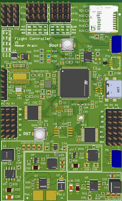
Flight Controller H743 V1
Overview
This flight controller runs natively on the stock MatekH743 ArduPilot target, with no custom code compilation needed. The battery voltage sensor uses a 10k:100k voltage divider and the battery pads offer some overvoltage and reverse polarity protection (though the MOSFET might get damaged and could potentially need to be replaced, but the main board will remain safe). The board also has a SPI flash memory chip on the same SPI pins as the IMU and CS (chip select pin) connected to PE2 on the STM32H7. This remains unused by default on ArduPilot, but is available if needed on custom firmware. The air speed (AirS), RSSI and current sensor header pins only accept a maximum of 3.3V, if the sensor exceeds that you will need to add an external voltage divider.
Components
MCU: STM32H743VIT6, 480MHz, 2MB Flash
IMU: ICM-42688-P
Barometer: DPS368XTSA1
Analog OSD: AT7456E
Blackbox: MicroSD card slot
Peripherals
7x UARTs (1,2,3,4,6,7,8)
13x PWM outputs
1x I2C
1x CAN
4x ADC (VBAT, Current, RSSI, AirSpeed)
3x LEDs for Status (red, blue) and 3.3V indicator (green)
1x SPI3 header pins
USB Type-C (USB 2.0)
2x JST-SH_6pin (Digital VTX: Rx7, Tx7, Rx8 – GPS: Rx2, Tx2, I2C1)
1x JST-SH_4pin for CAN
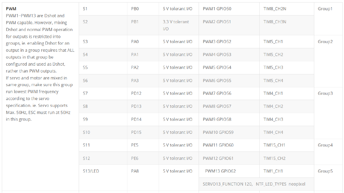
Since the pinout is the same as MATEK H743 V4 Slim, the timer groupings are identical as well. Below is a screenshot from MATEK’s website:
Power
Input: 2-6S LiPo
Current Sensor: Requires external sensor, connects to header pin
Rail 1 (S1 to S6): 5V 3A
Rail 2 (S7 to S13): 5V 3A
Component/Module Power (connects with LDO & UART header pins): 5V 2A
LDO: 3.3V 600mA
VTX Power: 9V 2A
FC Firmware
ArduPilot: MATEKH743
BetaFlight: MATEKH743
INAV: MATEKH743
Physical
Dimensions with JLCPCB Edge Rails: 71mm x 99mm
Dimensions without Edge Rails: 61mm x 99mm
Weight: 32g (with Edge Rails)
To maximize component density and keep the board footprint as small as possible, this layout does not use traditional 30.5mm stand-off holes.
Recommended Mounting: The board is designed to be soft-mounted flat against the airframe or inside a 3D-printed case using double-sided foam tape. This is a common practice for fixed-wing/VTOL builds and provides superior vibration isolation for the IMU compared to hard nylon standoffs.
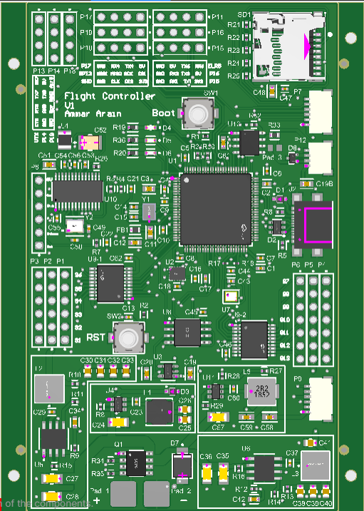
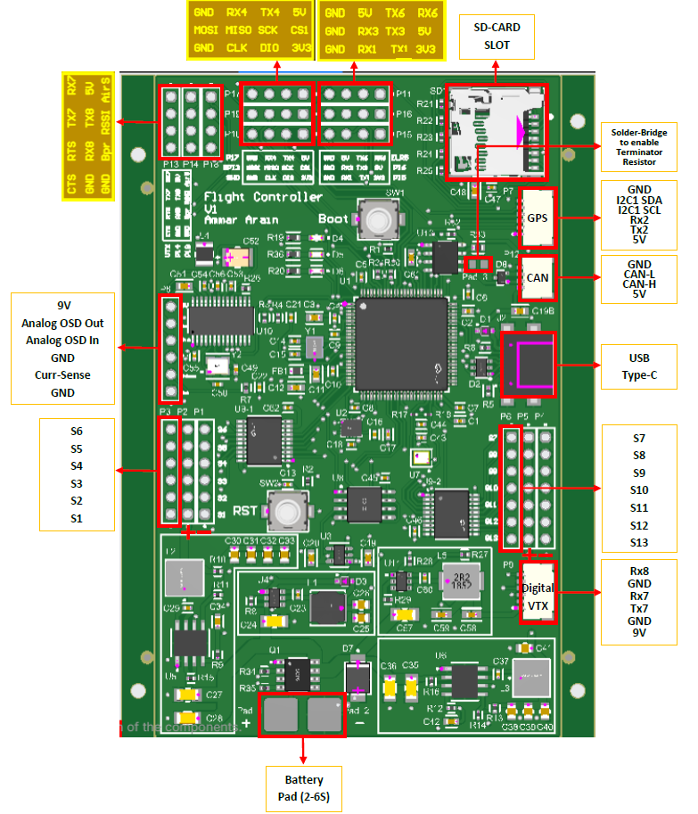
Flight Controller pins (shows JLCPCB edge rails on left and right side):
Includes
- 01_Fabrication folder contains the Gerber files.
- 02_Assembly folder contains the component placement and bill of material files for PCB assembly.
- 03_Schematic contains the electronic schematic of everything that is on the flight controller. This schematic can speed up debugging and will be helpful if you decide to make any custom firmware.
- 04_3D_Model contains a 3D model of the flight controller (with some components missing as they were not available in Altium) which can be helpful when making an encloser for the flight controller.
- 05_Documentation contains the datasheet for the flight controller (which includes a pinout diagram) and the JLCPCB settings I used when ordering my boards.
Testing & Hardware Validation
Flight Tested: This design has been fully fabricated, built, and successfully flight-tested on an operational drone.
Peripheral Coverage: Core flight systems (MCU, power delivery, IMU, basic sensor suite) are fully verified in real-world flight using ArduPilot. Provided "as-is" for experimental/educational builds; please note, optional peripheral or secondary features remain untested.
You are strongly recommended to review the schematic before production. Purchase includes digital files only; custom design revisions, bug fixes, or technical support are not included.
Refund Policy: Due to the immediate access and digital nature of these manufacturing files, all sales are final and non-refundable once downloaded.