
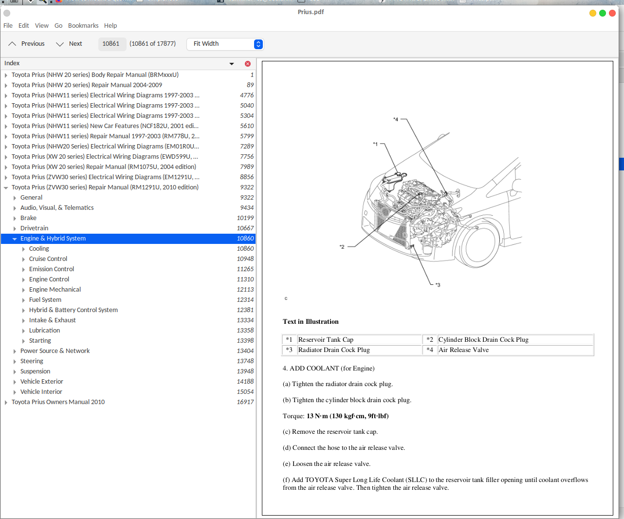
Toyota Prius All Models NHW11 NHW20 ZVW30 ZVW35 Workshop Service Repair Manual 1998-2014 PDF - MTOYPRIOPEK.zip
Full factory-style service and repair guide featuring Electrical Wiring Diagrams covering every 1998–2014 Toyota Prius trim, packed with the technical data needed to service, troubleshoot, fix, and rebuild the vehicle the way trained technicians do.
The 1998–2014 model year Toyota Prius All Models workshop service repair manual contains:
* Numbered table of contents easy to use so that you can find the information you need fast.
* Detailed sub-steps expand on repair procedure information
* Numbered instructions guide you through every repair procedure step by step.
* Troubleshooting and electrical service procedures are combined with detailed wiring diagrams for ease of use.
* Notes, cautions and warnings throughout each chapter pinpoint critical information.
* Bold figure number help you quickly match illustrations with instructions.
* Detailed illustrations, drawings and photos guide you through every procedure.
* Enlarged inset helps you identify and examine parts in detail.
PRODUCT DETAILS:
Total Pages: 17,331 pages
File Format: PDF / HTML etc.
Language: English
Toyota Prius (NHW 20 series) Repair Manual 2004-2009.pdf
Toyota Prius Repair Manual MK2007.pdf
Toyota Prius (NHW11 series) Electrical Wiring Diagrams 1997-2003 (EWD414U, 2001 edition).pdf
Toyota Prius (NHW11 series) Electrical Wiring Diagrams 1997-2003 (EWD464U, 2002 edition).pdf
Toyota Prius (NHW11 series) Electrical Wiring Diagrams 1997-2003 (EWD493U, 2003 edition).pdf
Toyota Prius (NHW11 series) New Car Features (NCF182U, 2001 edition).pdf
Toyota Prius (NHW11 series) Repair Manual 1997-2003 (RM778U, 2001 edition).pdf
Toyota Prius (NHW20 Series) Electrical Wiring Diagrams (EM01R0U, 2006).pdf
Toyota Prius (NHW20 series) Repair Manual (RM1076E).zip
Toyota Prius (NHW20 series) Repair Manual (SC03Q0U_2007 edition).zip
Toyota Prius (NHW 20 series) Body Repair Manual (BRMxxxU).pdf
Toyota Prius Owners Manual 2010.pdf
Toyota Prius Plug-in Hybrid (ZVW35 series) Repair Manual (RM14C0U_SC14C1UB).zip
Toyota Prius (XW 20 series) Electrical Wiring Diagrams (EWD599U, 2005 edition).pdf
Toyota Prius (XW 20 series) Repair Manual (RM1075U, 2004 edition).pdf
Toyota Prius (ZVW30 series) Electrical Wiring Diagrams (EM1291U, 2010 edition).pdf
Toyota Prius (ZVW30 series) Repair Manual 2009-2015 (RM25A0U_SC25A0UA).zip
Toyota Prius (ZVW30 series) Repair Manual (RM1291U, 2010 edition).pdf
Toyota Prius (ZVW30 series) Repair Manual (SC12A0E, 2009 edition).zip
TABLE OF CONTENTS
Toyota Prius (NHW 20 series) Body Repair Manual (BRMxxxU)......1
00_FOREWORD......3
00_VIEWS OF THIS TEXT......5
BODY DIMENSIONS - ......7
BODY DIMENSIONS - BODY DIMENSION DRAWINGS......8
BODY DIMENSIONS - BODY OPENING AREAS (Rear View)......9
BODY DIMENSIONS - BODY OPENING AREAS (Side View Front)......10
BODY DIMENSIONS - BODY OPENING AREAS (Side View Rear)......11
BODY DIMENSIONS - REFERENCE VALUE......12
BODY DIMENSIONS - UNDER BODY......13
BODY PANEL REPLACEMENT - CENTER BODY PILLAR (CUT)......15
BODY PANEL REPLACEMENT - COWL TOP INNER SIDE PANEL (ASSY)......18
BODY PANEL REPLACEMENT - COWL TOP SIDE PANEL (ASSY)......20
BODY PANEL REPLACEMENT - FIT STANDARDS......22
BODY PANEL REPLACEMENT - FRONT BODY PILLAR (CUT)......24
BODY PANEL REPLACEMENT - FRONT CROSSMEMBER (ASSY)......29
BODY PANEL REPLACEMENT - FRONT DOOR OUTER PANEL (ASSY)......33
BODY PANEL REPLACEMENT - FRONT FENDER APPON (ASSY)......35
BODY PANEL REPLACEMENT - FRONT FENDER APRON FRONT WITH SUPPORT (ASSY)......37
BODY PANEL REPLACEMENT - FRONT SIDE MEMBER (ASSY)......40
BODY PANEL REPLACEMENT - FRONT SIDE MEMBER (CUT-P)......43
BODY PANEL REPLACEMENT - RADIATOR SIDE SUPPORT (ASSY)......45
BODY PANEL REPLACEMENT - RADIATOR SUPPORT (ASSY)......47
BODY PANEL REPLACEMENT - RADIATOR UPPER SUPPORT (ASSY)......51
BODY PANEL REPLACEMENT - ROCKER OUTER PANEL (CUT-H)......54
INTRODUCTION - ABBREVIATIONS USED IN THIS MANUAL......56
INTRODUCTION - BODY PANEL REPLACEMENT THIS MANUAL......57
INTRODUCTION - FOR ALL OF VEHICLES......62
INTRODUCTION - GENERAL REPAIR INSTRUCTIONS......70
INTRODUCTION - HANDLING PRECAUTIONS ON RELATED COMPONENTS......74
INTRODUCTION - PRECAUTIONS FOR REPAIRING BODY STRUCTURE PANELS......75
INTRODUCTION - PROPER AND EFFICIENT WORK PROCEDURES......77
PAINT COATING - BODY PANEL SEALING AREAS......82
UNDER BODY - GENERAL......87
Toyota Prius (NHW 20 series) Repair Manual 2004-2009......89
AC - Air Conditioning......89
Air Conditioning......89
Air Conditioning System......89
Precaution......89
Parts Location......91
System Diagram......94
System Description......99
How to Proceed With Troubleshooting......112
Customize Parameters......115
Problem Symptoms Table......116
Terminals of ECU......118
Diagnosis System......122
DTC Check / Clear......123
Check Mode Procedure......124
Data List / Active Test......127
Diagnostic Trouble Code Chart......130
Blower Motor Circuit......202
Heater Relay Circuit......207
Heater Water Pump Circuit......210
PTC Heater Circuit......213
Steering Pad Switch Circuit......217
IG Power Source Circuit......224
Back-up Power Source Circuit......226
Refrigerant......228
On-Vehicle Inspection......228
Replacement......233
Refrigerant Line......236
Components......236
Air Conditioning Unit......237
Components......237
Removal......239
Disassembly......243
Reassembly......246
Installation......250
Blower Unit......254
Components......254
Removal......255
Disassembly......256
Reassembly......257
Installation......258
Electric Inverter Compressor......260
Removal......260
Installation......261
Condenser......264
Components......264
On-Vehicle Inspection......265
Removal......266
Disassembly......267
Reassembly......268
Installation......268
Heater Water Pump......271
Removal......271
Installation......271
Air conditioning Amplifier......273
Removal......273
Installation......273
AH - Axle......274
Axle......274
Axle System......274
Problem Symptoms Table......274
Front Axle Hub Bolt......275
Removal......275
Installation......276
Front Axle Hub......277
Components......277
On-Vehicle Inspection......278
Removal......279
Installation......281
Rear Axle Hub Bolt......283
Removal......283
Installation......284
Rear Axle Hub and Bearing......285
Components......285
On-Vehicle Inspection......286
Removal......287
Installation......288
AV - Audio Visual......289
Audio / Visual......289
Audio Visual System......289
Precaution......289
Parts Location......290
System Diagram......292
System Description......294
How to Proceed with Troubleshooting......300
Identifation of Noise Source......303
Display Check Mode......305
Bluetooth Tel Check Mode......309
Diagnosis Display Detailed Description......312
Problem Symptoms Table......319
Terminals of ECU......321
DTC Check / Clear......327
Diagnostic Trouble Code Chart......332
Noise Occurs......384
Pressing Power Switch does not Turn on System......386
No Sound can be Heard from Speakers......387
Sound Quality is Bad Only when CD is Played (Volume is Too Low)......388
CD cannot be Ejected......389
CD cannot be Inserted / Played or CD is Ejected Right After Insertion......390
CD Sound Skips......392
Radio Broadcast cannot be Received or Poor Reception......394
Poor Sound Quality in All Modes (Low Volume)......397
Cellular Phone Registration Failure, Phone Directory Transfer Failure......398
Cellular Phone cannot Send / Receive......400
Cannot Call in a Certain Place......402
The Other Caller's Voice cannot be Heard, is too Quiet, or Distorted......403
The Other Caller cannot Hear Your Voice, or Your Voice is too Quiet or Distorted......404
Vehicle Speed Signal Circuit between Radio Receiver and Combination Meter......406
Steering Pad Switch Circuit......409
Illumination Circuit......413
Speaker Circuit......420
Sound Signal Circuit between Radio Receiver and Stereo Component Amplifier......432
Sound Signal Circuit between Radio Receiver and Stereo Jack Adapter......434
Mute Signal Circuit between Radio Receiver and Stereo Component Amplifier......436
AVC-LAN Circuit......438
Vehicle Speed Signal Circuit between Stereo Component Amplifier and Combination Meter......440
Microphone Circuit between Overhead J/B and Multi-display......443
Gateway ECU Communication Error......445
Radio Receiver Communication Error......449
Stereo Component Amplifier Communication Error......453
Multi-display Communication Error......457
Radio Receiver Power Source Circuit......461
Stereo Component Amplifier Power Source Circuit......463
Multi-display Power Source Circuit......465
Gateway ECU Power Source Circuit......467
Radio Receiver......469
Components......469
Removal......471
Installation......472
Stereo Component Amplifier......474
Components......474
Removal......475
Installation......475
Front NO.1 Speaker......477
Components......477
Removal......478
Installation......479
Front NO.2 Speaker......481
Components......481
Removal......482
Installation......483
Stereo Component Speaker......484
Components......484
Removal......485
Installation......485
Rear Speaker......486
Components......486
Removal......487
Installation......488
Rear NO.2 Speaker......490
Components......490
Removal......491
Installation......492
Radio Antenna Cord......493
Components......493
Removal......494
Installation......496
Radio Antenna Holder......498
Components......498
Removal......499
Installation......499
Radio Antenna Pole......501
Components......501
Removal......502
Installation......503
Network Gateway ECU......504
Components......504
Removal......505
Installation......505
Steering Pad Switch......506
Precaution......506
Components......507
Removal......508
Installation......508
Microphone Amplifier......510
Components......510
Removal......511
Installation......512
BC - Brake Control......513
Brake Control......513
Electronically Controlled Brake System......513
Precaution......513
Parts Location......516
System Diagram......518
System Description......523
How to Proceed with Troubleshooting......528
Check for Intermittent Problems......530
Initialization......532
Calibration......535
Test Mode Procedure......536
Problem Symptoms Table......541
Terminals of ECU......543
Diagnosis System......550
DTC Check / Clear......551
Freeze Frame Data......554
Fail-Safe Chart......556
Data List / Active Test......557
Diagnostic Trouble Code Chart......562
ABS Warning Light Remains ON......681
ABS Warning Light does not Come ON......685
VSC Warning Light Remains ON......686
VSC Warning Light does not Come ON......690
Brake Warning Light Circuit......691
Brake Control Warning Light Remains ON......697
Brake Control Warning Light does not Come ON......701
Slip Indicator Light Circuit......702
Skid Control Buzzer Circuit......706
TC and CG Terminal Circuit......709
TS and CG Terminal Circuit......713
Brake Actuator......716
Components......716
On-Vehicle Inspection......720
Replacement......724
Disposal......732
Front Speed Sensor......733
Components......733
Removal......734
Installation......735
Skid Control Sensor......736
Components......736
Removal......737
Installation......738
Yaw Rate and Deceleration Sensor......739
Components......739
Removal......740
Installation......740
Steering Angle Sensor......741
Components......741
Removal......742
Installation......742
Skid Control ECU......744
Componente......744