
John Deere 310L EP Backhoe Loader Operation & Tests Workshop Manual TM13289X19 PDF - MJODTM13289X19.zip
Operation & Tests Technical Manual for the John Deere 310L EP Backhoe Loader (TM13289X19).PDF
TM13289X19 — the Operation & Tests technical manual for the John Deere 310L EP Backhoe Loader, delivered in PDF format.
Complete official Operation & Test service manual with Electrical Wiring Diagrams for John Deere 310L EP Backhoe Loader (PIN: 1T0310EL**G273920-329327)(Electrical Wiring Diagrams included), with all the shop information to maintain, diagnose, repair, and rebuild like professional mechanics.
John Deere 310L EP Backhoe Loader workshop Operation & Test manual includes:
* Numbered table of contents easy to use so that you can find the information you need fast.
* Detailed sub-steps expand on repair procedure information
* Numbered instructions guide you through every repair procedure step by step.
* Troubleshooting and electrical service procedures are combined with detailed wiring diagrams for ease of use.
* Notes, cautions and warnings throughout each chapter pinpoint critical information.
* Bold figure number help you quickly match illustrations with instructions.
* Detailed illustrations, drawings and photos guide you through every procedure.
* Enlarged inset helps you identify and examine parts in detail.
Total Pages: 1,261 pages
File Format: PDF (bookmarked, Searchable, Printable, high quality)
Language: English
MAIN SECTIONS
Foreword
Manual Identification-READ THIS FIRST!
General Information
Safety
Diagnostics
Engine Control Unit (ECU) Diagnostic Trouble Codes
Engagement and Monitor Unit (EMU) Diagnostic Trouble Codes
Transmission Control Unit (TCU) Diagnostic Trouble Codes
Vehicle Control Unit (VCU) Diagnostic Trouble Codes
Auxiliary Valve Controller (AVC) Diagnostic Trouble Codes
Vehicle Control Unit 2 (VC2) Diagnostic Trouble Codes
Operational Checkout Procedure
Operational Checkout Procedure
Engine
Theory of Operation
System Diagrams
Diagnostic Information
Adjustments
Tests
Electrical System
Theory of Operation
System Diagrams
Diagnostic Information
Monitor Operation
Diagnostic Test Box
Tests
Power Train
Theory of Operation
System Diagrams
Diagnostic Information
Adjustments
Tests
Hydraulic System
Theory of Operation
System Diagrams
Diagnostic Information
Adjustments
Tests
Heating and Air Conditioning
Theory of Operation
System Diagrams
Diagnostic Information
Tests
TABLE OF CONTENTS
9000 - General Information
01 - Safety
Add and Operate Attachments Safely
Avoid Backover Accidents
Avoid High-Pressure Fluids
Avoid High-Pressure Oils
Avoid Machine Tipover
Avoid Static Electricity Risk When Refueling
Avoid Unauthorized Machine Modifications
Avoid Work Site Hazards
Clean Debris from Machine
Decommissioning Proper Recycling and Disposal of Fluids and Components
Drive Metal Pins Safely
Follow Safety Instructions
Follow Tire Recommendations
Handle Chemical Products Safely
In Case of Machine Fire
Inspect and Maintain ROPS
Inspect Machine
Keep Riders Off Machine
Make Welding Repairs Safely
Operate Only If Qualified
Operating or Traveling On Public Roads
Park and Prepare for Service Safely
Prepare for Emergencies
Prevent Acid Burns
Prevent Battery Explosions
Prevent Fires
Prevent Unintended Machine Movement342200224If Equipped With Pilot Controls
Prevent Unintended Machine Movement
Recognize Safety Information
Remove Paint Before Welding or Heating
Service Cooling System Safely
Service Tires Safely
Start Only From Operator's Seat
Stay Clear of Moving Parts
Travel Safely
Use and Maintain Seat Belt
Use Special Care When Operating
Use Steps and Handholds Correctly
Wear Protective Equipment
Work In Ventilated Area
9001 - Diagnostic Trouble Codes (DTC)
10 - Engine Control Unit (ECU) Diagnostic Trouble Codes
000029.03 342200224 Hand Throttle
000029.04 342200224 Hand Throttle
000029.14 342200224 Hand Throttle
000091.03 342200224 Foot Throttle
000091.04 342200224 Foot Throttle
000091.14 342200224 Foot Throttle
001321.05 342200224 Starter Relay
001321.06 342200224 Starter Relay
001321.09 342200224 Starter Relay
001321.16 342200224 Starter Relay
001321.31 342200224 Starter Relay
002003.09 342200224 No CAN From TCU
002071.09 342200224 No CAN From VCU
003353.31 342200224 Alternator Output
524225.31 342200224 Engine Start
Engine Control Unit (ECU) Diagnostic Trouble Codes
20 - Engagement and Monitor Unit (EMU) Diagnostic Trouble Codes
000096.03 342200224 Fuel Level Sensor
000096.04 342200224 Fuel Level Sensor
000628.12 342200224 Programming
000920.06 342200224 Alarm Output
000920.12 342200224 Alarm Output
001196.11 342200224 Security
002000.09 342200224 No CAN from ECU
002003.09 342200224 No CAN from TCU
002071.09 342200224 No CAN from VCU
002251.09 342200224 No CAN from MTG
003509.03 342200224 Sensor Supply 1
003509.04 342200224 Sensor Supply 1
524082.07 342200224 Display Buttons
Engagement and Monitor Unit (EMU) Diagnostic Trouble Codes
30 - Transmission Control Unit (TCU) Diagnostic Trouble Codes
000070.04 342200224 Park Brake
000070.07 342200224 Park Brake
000177.00 342200224 Transmission Oil Temp
000177.04 342200224 Transmission Oil Temp
000525.02 342200224 Requested Gear
000525.03 342200224 Requested Gear
000525.04 342200224 Requested Gear
000525.05 342200224 Requested Gear
000604.04 342200224 TCL Neutral SW
000629.12 342200224 Controller Fault
000736.03 342200224 Y3 Solenoid
000736.05 342200224 Y3 Solenoid
000736.06 342200224 Y3 Solenoid
000737.03 342200224 Y4 Solenoid
000737.05 342200224 Y4 Solenoid
000737.06 342200224 Y4 Solenoid
000738.03 342200224 Y5 Solenoid
000738.05 342200224 Y5 Solenoid
000738.06 342200224 Y5 Solenoid
000746.05 342200224 Differential Lock
000746.06 342200224 Differential Lock
000767.05 342200224 TCL Reverse SW
000880.06 342200224 Brake Lights
000903.05 342200224 TCL Forward SW
002000.09 342200224 System Message
002023.09 342200224 System Message
002071.09 342200224 System Message
002072.09 342200224 System Message
002612.05 342200224 MFWD Solenoid
002612.06 342200224 MFWD Solenoid
004312.02 342200224 TCL Selector
004312.03 342200224 TCL Selector
004312.05 342200224 TCL Selector
004312.06 342200224 TCL Direction Power
522379.03 342200224 Park Brake
522379.04 342200224 Park Brake
522379.06 342200224 Park Brake
522405.03 342200224 PB Pressure Switch
524172.03 342200224 Clutch Disconnect
524172.04 342200224 Clutch Disconnect
524172.09 342200224 Clutch Disconnect
Transmission Control Unit (TCU) Diagnostic Trouble Codes
40 - Vehicle Control Unit (VCU) Diagnostic Trouble Codes
000237.13 342200224 VIN Mismatch
000237.31 342200224 VIN Missing
000628.12 342200224 Program Memory
001713.00 342200224 Hyd Oil Restriction
520688.03 342200224 Pilot Enable Driver
520688.06 342200224 Pilot Enable Driver
520713.03 342200224 Seat Position
520713.04 342200224 Seat Position
520713.13 342200224 Seat Position
523911.03 342200224 Pump Control
523911.05 342200224 Pump Control
523911.06 342200224 Pump Control
Vehicle Control Unit (VCU) Diagnostic Trouble Codes
50 - Sealed Switch Module (SSM) Diagnostic Trouble Codes
000168.03 342200224 Battery Voltage
000237.02 342200224 Vehicle ID
000237.13 342200224 Vehicle ID
000237.31 342200224 Vehicle ID
000629.12 342200224 Control Unit
002701.03 342200224 BH Aux Roller
002701.04 342200224 BH Aux Roller
002701.07 342200224 BH Aux Roller
002738.03 342200224 Extendable Roller
002738.04 342200224 Extendable Roller
002738.07 342200224 Extendable Roller
520425.07 342200224 System Message
520426.07 342200224 System Message
520542.03 342200224 System Message
520543.04 342200224 System Message
523934.00 342200224 Extendable Sol A
523934.01 342200224 Extendable Sol A
523934.03 342200224 Extendable Sol A
523934.04 342200224 Extendable Sol A
523934.05 342200224 Extendable Sol A
523934.06 342200224 Extendable Sol A
523940.00 342200224 Extendable Sol B
523940.01 342200224 Extendable Sol B
523940.03 342200224 Extendable Sol B
523940.04 342200224 Extendable Sol B
523940.05 342200224 Extendable Sol B
523940.06 342200224 Extendable Sol B
524010.00 342200224 Selective Flow
524010.01 342200224 Selective Flow
524010.03 342200224 Selective Flow
524010.04 342200224 Selective Flow
524010.05 342200224 Selective Flow
524010.06 342200224 Selective Flow
Sealed Switch Module (SSM) Diagnostic Trouble Codes
70 - Vehicle Control Unit 2 (VC2) Diagnostic Trouble Codes
002664.03 342200224 Ldr Aux Roller
002664.04 342200224 Ldr Aux Roller
002664.07 342200224 Ldr Aux Roller
003509.03 342200224 SENSOR SUPPLY 1
003509.04 342200224 SENSOR SUPPLY 1
520669.00 342200224 Loader Aux Pressure
520669.01 342200224 Loader Aux Pressure
520669.03 342200224 Loader Aux Sol A
520669.04 342200224 Loader Aux Sol A
520669.05 342200224 Loader Aux Sol A
520669.06 342200224 Loader Aux Sol A
523404.00 342200224 Backhoe Aux Pressure
523404.01 342200224 Backhoe Aux Pressure
523935.03 342200224 Backhoe Aux Sol A
523935.04 342200224 Backhoe Aux Sol A
523935.05 342200224 Backhoe Aux Sol A
523935.06 342200224 Backhoe Aux Sol A
Vehicle Control Unit 2 (VC2) Diagnostic Trouble Codes
9005 - Operational Checkout Procedure
10 - Operational Checkout Procedure
Operational Checkout Procedure
9010 - Engine
05 - Theory of Operation
Cold Start Aid System Operation
Engine Cooling System Operation
John Deere Engine Operation
10 - System Diagrams
Engine Cooling System Component Location
Engine Fuel System Component Location
Engine Intake and Exhaust Component Location
15 - Diagnostic Information
Engine Identification
John Deere Engine Operation
20 - Adjustments
John Deere Engine Operation
25 - Tests
Air in Fuel Test
Engine Speed Check
Engine Thermostat Test
Fluid Sampling Procedure342200224If Equipped
Intake Manifold Pressure342200224Turbocharger Boost
John Deere Engine Operation
Thermal Bypass Valve Test
9015 - Electrical System
05 - System Information
Auxiliary Valve Controller (AVC) Circuit Theory of Operation
Controller Area Network (CAN) Circuit Theory of Operation
Engagement and Monitor Unit (EMU) Circuit Theory of Operation
Engine Control Unit (ECU) Circuit Theory of Operation
Hydraulic System Circuit Theory of Operation
JDLink342204242 Circuit Theory of Operation
Start and Charge Circuit Theory of Operation
Transmission Control Circuit Theory of Operation
10 - System Diagrams
Air Conditioner Compressor Clutch Harness (W39) Component Location
Air Conditioner Compressor Clutch Harness (W39) Wiring Diagram
Auxiliary Hydraulic Foot Switch Harness (W47) Component Location342200224If Equipped
Auxiliary Hydraulic Foot Switch Harness (W47) Wiring Diagram342200224If Equipped
Auxiliary Valve Control Harness (W23) Component Location
Auxiliary Valve Control Harness (W23) Wiring Diagram
Blower Mode Door Motor Harness (W56) Component Location
Blower Mode Door Motor Harness (W56) Wiring Diagram
Cab Harness (W14) Component Location
Cab Harness (W14) Wiring Diagram
Canopy Harness (W15) Component Location
Canopy Harness (W15) Wiring Diagram
Canopy (With Windshield) Harness (W16) Component Location
Canopy (With Windshield) Harness (W16) Wiring Diagram
Electrical Diagram Information
Electrical Schematic Symbols
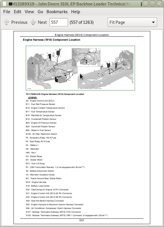
Engine Harness (W10) Component Location
Engine Harness (W10) Wiring Diagram