
New Holland TG210 TG230 TG255 TG285 Tractor Workshop Repair Service Manual PDF - MNHTG210TG285OPES.zip
New Holland TG210, TG230, TG255, TG285 Tractor Workshop & Service Guide
87057613 - Service Manual for New Holland TG Series Tractors (TG210, TG230, TG255, TG285).pdf
Complete service repair manual with Electrical Wiring Diagrams for New Holland Tractors TG210, TG230, TG255, TG285, with all the technical information to maintain, diagnose, repair, rebuild like professional mechanics.
New Holland TG Series Tractors (TG210, TG230, TG255, TG285) workshop service repair manual includes:
* Numbered table of contents easy to use so that you can find the information you need fast.
* Detailed sub-steps expand on repair procedure information
* Numbered instructions guide you through every repair procedure step by step.
* Troubleshooting and electrical service procedures are combined with detailed wiring diagrams for ease of use.
* Notes, cautions and warnings throughout each chapter pinpoint critical information.
* Bold figure number help you quickly match illustrations with instructions.
* Detailed illustrations, drawings and photos guide you through every procedure.
* Enlarged inset helps you identify and examine parts in detail.
PRODUCT DETAILS:
Total Pages: 3,101 pages
File Format: PDF (Internal Links, Bookmarked, Table of Contents, Searchable, Printable, high quality)
Language: English
MAIN SECTIONS
TG210, TG230, TG255, TG285 REPAIR MANUAL...1
COMPLETE CONTENTS...1
SECTION 00...1
Standard Torque Specifications - Section 00 Chapter 1...1
Safety, General Information/Maintenance Schedule - Section 00 Chapter 2...1
General Specifications and Special Torques - Section 00 Chapter 3...1
SECTION 10...1
Engine Removal and Installation - Section 10 Chapter 1...1
Fuel Tank Removal and Installation - Section 10 Chapter 2...1
Radiator, Coolers and Condenser - Removal and Installation - Section 10 Chapter 4...1
8.3L, 24 Valve Engine Introduction - Section 10 Chapter 5...1
8.3L, 24 Valve Engine Identification - Section 10 Chapter 6...1
8.3L, 24 Valve Engine Troubleshooting Symptoms - Section 10 Chapter 7...1
8.3L, 24 Valve Engine Cylinder Block - Section 10 Chapter 8...1
8.3L, 24 Valve Engine Cylinder Head - Section 10 Chapter 9...1
8.3L, 24 Valve Engine Rocker Levers Section 10 Chapter 10...1
8.3L, 24 Valve Engine Cam Followers - Section 10 Chapter 11...1
8.3L, 24 Valve Engine Fuel System - Section 10 Chapter 12...1
8.3L, 24 Valve Engine Injectors and Fuel Lines - Section 10 Chapter 13...1
8.3L, 24 Valve Engine Lubricating Oil System - Section 10 Chapter 14...1
8.3L, 24 Valve Engine Cooling System - Section 10 Chapter 15...1
8.3L, 24 Valve Engine Drive Units Section 10 Chapter 16...1
8.3L, 24 Valve Engine Air Intake System - Section 10 Chapter 17...1
8.3L, 24 Valve Engine Exhaust System - Section 10 Chapter 18...1
8.3L, 24 Valve Engine Miscellaneous - Section 10 Chapter 19...1
8.3L, 24 Valve Engine Specifications - Section 10 Chapter 20...1
8.3L, 24 Valve Engine Fuel System - Introduction - Section 10 Chapter 21...1
8.3L, 24 Valve Engine Fuel System - System Identification - Section 10 Chapter 22...1
8.3L, 24 Valve Engine Fuel System - Familiarization - Section 10 Chapter 23...1
8.3L, 24 Valve Engine Fuel System - Troubleshooting Fault Codes - Section 10 Chapter 24...1
8.3L, 24 Valve Engine Fuel System - Troubleshooting Symptoms - Section 10 Chapter 25...1
8.3L, 24 Valve Engine Fuel System - Electronic Engine Controls - Section 10 Chapter 26...1
8.3L, 24 Valve Engine Fuel System - Specifications - Section 10 Chapter 27...2
SECTION 14...2
Power Take Off Control System How it Works - Section 14 Chapter 1...2
SECTION 21...2
Powershift Transmission System How it Works and Troubleshooting - Section 21 Chapter 1...2
Front Frame to Speed Transmission Split - Section 21 Chapter 2...2
Speed to Range Transmission Split - Section 21 Chapter 3...2
Speed Transmission - Section 21 Chapter 4...2
Range Transmission to Rear Frame Split - Section 21 Chapter 5...2
Range Transmission - Section 21 Chapter 6...2
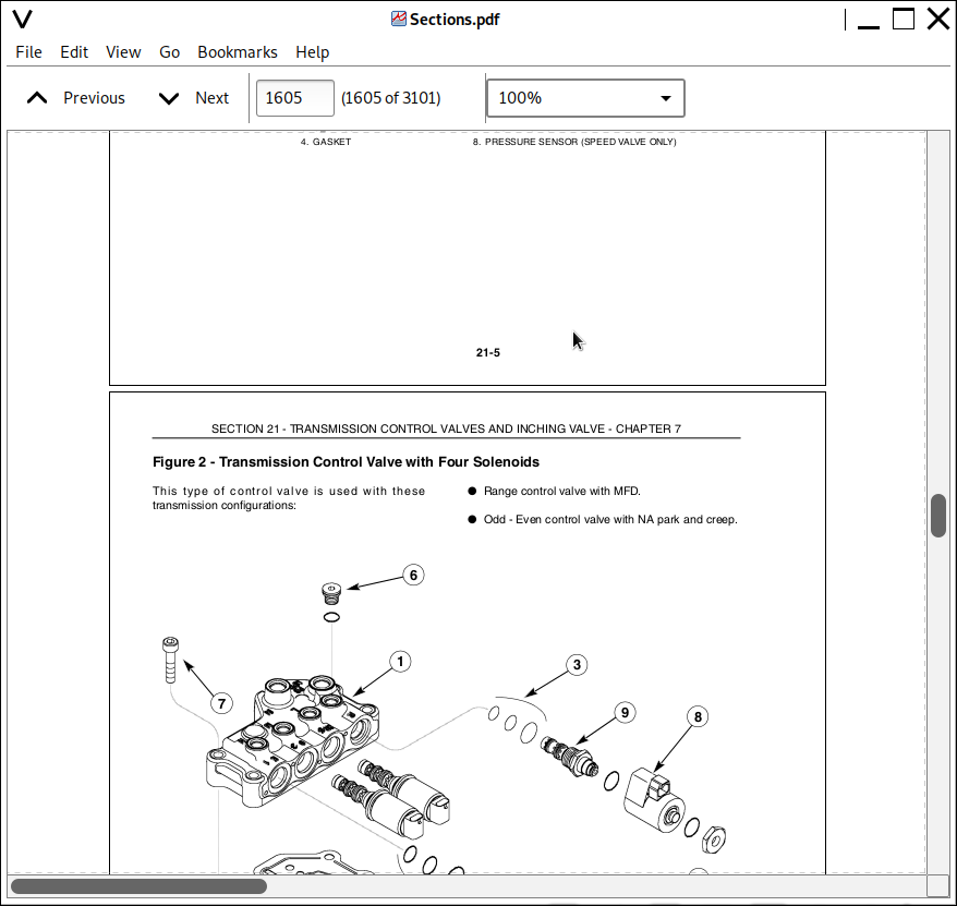
Transmission Control Valves and inching Valve - Section 21 Chapter 7...2
Rear Frame - Section 21 Chapter 8...2
Hydraulic Pump Drive - Section 21 Chapter 9...2
SECTION 25...2
Mechanical Front Drive MFD Control System How it Works - Section 25 Chapter 1...2
Differential Lock Control System How it Works - Section 25 Chapter 2...2
MFD Clutch Removal Without Tractor Split - Section 25 Chapter 3...2
MFD Driveshaft Removal and Installation - Section 25 Chapter 4...2
Suspended MFD Axle Removal - Section 25 Chapter 6...2
Supersteer Axle Removal - Section 25 Chapter 7...2
Limited Slip FWD Differential - Section 25 Chapter 8...2
Locking MFD Differential - Section 25 Chapter 9...2
MFD Planetary Hub, Steering Knuckle, and Axle Drive Shaft - Section 25 Chapter 10...2
Suspended FWD Axle - Section 25 Chapter 11...2
Supersteer Axle Vertical Control Linkage - Section 25 Chapter 12...2
Suspended FWD Axle System - Section 25 Chapter 13...2
SECTION 27...2
Rear Axle and Planetaries - Section 27 Chapter 1...2
SECTION 33...2
Brake Valve - Section 33 Chapter 1...2
Brake Cylinders - Section 33 Chapter 2...2
Park Brake - Section 33 Chapter 3...2
Trailer Brakes How It Works - Section 33 Chapter 4...3
SECTION 35...3
How to Read Symbols in a Hydraulic Schematic - Section 35 Chapter 1...3
Hydraulic Systems How it Works and Troubleshooting - Section 35 Chapter 2...3
PTO and Differential Lock Valve - Section 35 Chapter 3...3
Remote Valve and Coupler Service - Section 35 Chapter 4...3
Remote Hydraulic System How it Works and Troubleshooting - Section 35 Chapter 5...3
Priority and Regulator Valve - Section 35 Chapter 6...3
Charge Pump - Section 35 Chapter 7...3
CCLS Piston Pump And Hydraulic Filter - Section 35 Chapter 8...3
Hitch System How it Works - Section 35 Chapter 9...3
Hitch Control Valve - Section 35 Chapter 10...3
SECTION 41...3
Steering Column and Steering Hand Pump Removal And Installation - Section 41 Chapter 1...3
SECTION 50...3
Air Conditioning Troubleshooting - Section 50 Chapter 1...3
Air Conditioner System Service - Section 50 Chapter 2...3
SECTION 55...3
Electrical System How It Works and Troubleshooting (Prior to P.I.N. JAW 129992) - Section 55 Chapter 1...3
Electrical System How It Works and Troubleshooting (P.I.N. JAW129992 and After) - Section 55 Chapter 1A...3
Standard Instrumentation Programming and Fault Codes - Section 55 Chapter 2...3
Hitch Controller Calibration and Fault Codes - Section 55 Chapter 3...3
Transmission Controller (With Suspended Axle) Calibration and Fault Codes - Section 55 Chapter 4...3
Armrest Controller Calibration and Fault Codes - Section 55 Chapter 5...3
Remote Hydraulics Controller Fault Codes - Section 55 Chapter 6...3
PTO Controller Configuration and Fault Codes - Section 55 Chapter 7...3
Performance Monitor Controller Fault Codes - Section 55 Chapter 8...3
SECTION 90...3
Pedal and Pedal Switch Adjustment - Section 90 Chapter 1...3
Cab Raise/Removal and Installation - Section 90 Chapter 2...3
ELECTRICAL SCHEMATIC ( Prior to P.I.N. JAW129992)...1
ELECTRICAL SCHEMATIC (P.I.N. JAW129992 and After)...4
HYDRAULIC SCHEMATIC...1
A/C TROUBLESHOOTING CHART...1
TABLE OF CONTENTS
Standard Torque Specifications
Safety, General Information/Maintenance Schedule
General Specifications and Special Torques
Engine Removal and Installation
Fuel Tank Removal and Installation
Radiator, Coolers and Condenser - Removal and Installation
8.3L, 24 Valve Engine Introduction
8.3L, 24 Valve Engine Identification
8.3L, 24 Valve Engine Troubleshooting Symptoms
8.3L, 24 Valve Engine Cylinder Block
8.3L, 24 Valve Engine Cylinder Head
8.3L, 24 Valve Engine Rocker Levers
8.3L, 24 Valve Engine Cam Followers
8.3L, 24 Valve Engine Fuel System
8.3L, 24 Valve Engine Injectors and Fuel Lines
8.3L, 24 Valve Engine Lubricating Oil System
8.3L, 24 Valve Engine Cooling System
8.3L, 24 Valve Engine Drive Units
8.3L, 24 Valve Engine Air Intake System
8.3L, 24 Valve Engine Exhaust System
8.3L, 24 Valve Engine Miscellaneous
8.3L, 24 Valve Engine Specifications
8.3L, 24 Valve Engine Fuel System - Introduction
8.3L, 24 Valve Engine Fuel System - System Identification
8.3L, 24 Valve Engine Fuel System - Familiarization
8.3L, 24 Valve Engine Fuel System - Troubleshooting Fault Codes
8.3L, 24 Valve Engine Fuel System - Troubleshooting Symptoms
8.3L, 24 Valve Engine Fuel System - Electronic Engine Controls
8.3L, 24 Valve Engine Fuel System - Specifications
Viscous Fan Drive Test (Service Bulletin)
Power Take Off Control System How it Works
Powershift Transmission System How it Works and Troubleshooting
Front Frame to Speed Transmission Split
Speed to Range Transmission Split
Speed Transmission
Range Transmission to Rear Frame Split
Range Transmission
Transmission Control Valves and inching Valve
Rear Frame
Hydraulic Pump Drive
Mechanical Front Drive MFD Control System How it Works
Differential Lock Control System How it Works
MFD Clutch Removal Without Tractor Split
MFD Driveshaft Removal and Installation
Suspended MFD Axle Removal
Supersteer Axle Removal
Limited Slip FWD Differential
Locking MFD Differential
MFD Planetary Hub, Steering Knuckle, and Axle Drive Shaft
Suspended FWD Axle
Supersteer Axle Vertical Control Linkage
Suspended FWD Axle System
Rear Axle and Planetaries
Brake Valve
Brake Cylinders
Park Brake
Trailer Brakes How It Works
How to Read Symbols in a Hydraulic Schematic
Hydraulic Systems How it Works and Troubleshooting
PTO and Differential Lock Valve
Remote Valve and Coupler Service
Remote Hydraulic System How it Works and Troubleshooting
Priority and Regulator Valve
Charge Pump
CCLS Piston Pump And Hydraulic Filter
Hitch System How it Works
Hitch Control Valve
Air Conditioning Troubleshooting
Air Conditioner System Service
Electrical System How It Works and Troubleshooting (Prior to P.I.N. JAW 129992)
Standard Instrumentation Programming and Fault Codes
Hitch Controller Calibration and Fault Codes
Transmission Controller
(With Suspended Axle) Calibration and Fault Codes
Armrest Controller Calibration and Fault Codes
Remote Hydraulics Controller Fault Codes
PTO Controller Configuration and Fault Codes
Performance Monitor Controller Fault Codes
Pedal and Pedal Switch Adjustment
Cab Raise/Removal and Installation
Service Information packaged with 87012641
INSITE Professional - Operation / ESDN - ECM Software Installation - 87012632 Electronic Service Tool - Users Guide 87025502
Electrical Schematic (Prior to P.I.N. JAW129992) - 87025177
Electrical Schematic (P.I.N. JAW129992 and After) - 87054643
Hydraulic Schematic - 87025178 Loctite Product Chart - 8-98902