
John Deere 4045 4-Valve Diesel Engine Component Technical Manual Level 34 ECU CTM120119 Worldwide Edition PDF - MJODCTM120119.zip
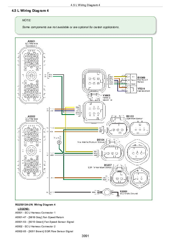
This is a full workshop-level repair guide for the John Deere 4045 4-Valve Diesel Engines, complete with electrical wiring diagrams and every technical detail needed to service, troubleshoot, fix, and overhaul these engines the way a professional technician would.
Contained in the John Deere 4045 4-Valve Diesel Engines workshop service repair manual:
* Numbered table of contents easy to use so that you can find the information you need fast.
* Detailed sub-steps expand on repair procedure information
* Numbered instructions guide you through every repair procedure step by step.
* Troubleshooting and electrical service procedures are combined with detailed wiring diagrams for ease of use.
* Notes, cautions and warnings throughout each chapter pinpoint critical information.
* Bold figure number help you quickly match illustrations with instructions.
* Detailed illustrations, drawings and photos guide you through every procedure.
* Enlarged inset helps you identify and examine parts in detail.
ctm120119 - 4045 4-Valve Diesel Engine — Level 34 ECU - (Worldwide Edition) Component Technical Manual (EN).pdf
ctm120163 - Motor diesel de 4 válvulas 4045 — ECU Nivel 34 - (Edición mundial) Manual técnico de componentes (ES)
ctm120154 - Motor a Diesel 4045 de 4 Válvulas — ECU Nível 34 - (Edição Mundial) Manual Técnico do Componente (PT).pdf
ctm120121 - 4045 neljaklapiline diiselmootor – tase 34 ECU - (Ülemaailmne versioon) komponendi tehniline juhend (ET).pdf
ctm120128 - Moteur diesel 4 soupapes 4045—Contrôleur ECU niveau 34 - (Édition mondiale) Manuel technique des composants (FR).pdf
ctm120129 - 4-Ventil-Dieselmotor 4045 — ECU (Level 34) - (Weltweite Ausgabe) Technisches Komponentenhandbuch (DE).pdf
ctm120139 - Motore diesel 4045 a 4 valvole — Livello ECU 34 - (Edizione universale) Manuale tecnico dei componenti (IT).pdf
ctm120114 - 4045 柴油发动机 (4气门) — 34 级 ECU - 世界通用机型 维修手册 (CN).pdf
ctm120140 - 4045 4 バルブディーゼルエンジン — レベル 34 ECU - 世界各国版 コンポーネント テクニカル マニュアル (JP).pdf
ctm120144 - 4045 4-밸브 디젤 엔진 — 레벨 34 ECU - (전세계 판) 구성품 기술 매뉴얼 (KR).pdf
PRODUCT DETAILS:
Total Pages: 4,039 pages
File Format: PDF (Internal Links, Bookmarked, Table of Contents, Searchable, Printable, high quality)
Language: EN DE FR ...
TABLE OF CONTENTS
ctm120119 - 4045 4-Valve Diesel Engine — Level 34 ECU - (Worldwide Edition) Component Technical Manual (EN)................2
TABLE OF CONTENTS................2
Section 01: General Information................63
Group 000: Safety................63
Understand Signal Words................67
Recognize Safety Information................68
Replace Safety Signs................69
Follow Safety Instructions................70
California Proposition 65 Warning................71
Exhaust Filter Cleaning................72
Avoid Hot Exhaust................73
Work In Ventilated Area................74
Decommissioning — Proper Recycling and Disposal of Fluids and Components................75
Prevent Machine Runaway................76
Practice Safe Maintenance................77
Work in Clean Area................79
Wear Protective Clothing................80
Service Machines Safely................81
Use Proper Tools................82
Construct Dealer-Made Tools Safely................83
Support Machine Properly................84
Use Proper Lifting Equipment................85
Protect Against Noise................86
Illuminate Work Area Safely................87
Install All Guards................88
Stay Clear of Rotating Drivelines................89
Protect Against High Pressure Spray................90
Service Cooling System Safely................91
Remove Paint Before Welding or Heating................92
Precautions for Welding................93
Wait Before Opening High-Pressure Fuel System................95
Avoid High-Pressure Fluids................96
Avoid Heating Near Pressurized Fluid Lines................97
Avoid Static Electricity Risk When Refueling................98
Handle Fluids Safely—Avoid Fires................100
Prepare for Emergencies................101
Handling Batteries Safely................102
Prevent Acid Burns................104
Prevent Battery Explosions................106
Live With Safety................107
Group 001: Engine Identification................64
Engine Serial Number Plate Information................110
OEM Engine Option Code Label................112
Information Relative to Emissions Regulations................116
Emissions Control System Certification Label................117
Group 002: Fuels, Lubricants, and Coolant................64
Diesel Exhaust Fluid (DEF) — Use in Selective Catalytic Reduction (SCR) Equipped Engines................119
Storing Diesel Exhaust Fluid (DEF)................120
Refilling Diesel Exhaust Fluid (DEF) Tank................121
Testing Diesel Exhaust Fluid (DEF)................123
Disposal of Diesel Exhaust Fluid (DEF)................124
Diesel Fuel................125
Supplemental Diesel Fuel Additives................127
Lubricity of Diesel Fuel................128
Handling and Storing Diesel Fuel................129
Biodiesel Fuel................130
Testing Diesel Fuel................132
Fuel Filters................133
Minimizing the Effect of Cold Weather on Diesel Engines................134
John Deere Break-In Plus™ Engine Oil — Interim Tier 4, Final Tier 4, Stage IIIB, Stage IV, and Stage V................136
Diesel Engine Oil — Interim Tier 4, Final Tier 4, Stage IIIB, Stage IV, and Stage V................137
Diesel Engine Oil and Filter Service Intervals — Interim Tier 4, Final Tier 4, Stage IIIB, Stage IV, and Stage V— OEM Applications................139
Diesel Engine Oil and Filter Service Intervals................141
Mixing of Lubricants................142
Alternative and Synthetic Lubricants................143
Lubricant Storage................144
Oil Filters................145
Diesel Engine Coolant (engine with wet sleeve cylinder liners)................146
Water Quality for Mixing with Coolant Concentrate................148
Operating in Warm Temperature Climates................149
Testing Coolant Freeze Point................150
Disposing of Coolant................152
Section 02: Repair and Adjustments................153
Group 010: Engine Rebuild................153
Check Air Intake System................171
Check and Service Cooling System................172
Check Crankcase Vent System................173
Check Electrical System................174
Check Exhaust System................176
Clean Engine................177
Engine Break-In Guidelines................178
Engine Overhaul Guidelines................182
General Tune-Up Recommendations................183
Engine Repair Stand................184
Install JT07268 Engine Mounting Adapter to D05223ST Repair Stand................185
Install JDG11853 Engine Mounting Adapter to D05223ST Repair Stand................187
Lift Straps — Installation................188
Lift Straps — Removal................190
Lifting Procedure................191
Mount Engine to Repair Stand Using JT07268................3952
Mount Engine to Repair Stand Using JDG11853................3937
Safety Precautions................197
Sealant Application Guidelines................198
Group 020: Cylinder Head and Valve Repair and Adjustment................153
Baffle, Rocker Arm Cover — Installation................250
Baffle, Rocker Arm Cover — Removal................253
Cylinder Block Top Deck — Cleaning and Inspection................203
Cylinder Head — Cleaning and Inspection................204
Cylinder Head — Flatness Check................205
Cylinder Head — Installation................206
Cylinder Head — Removal................211
Cylinder Head — Thickness Measurement................214
Cylinder Head Gasket — Inspection................216
Fuel Injector Sleeves — Installation................218
Fuel Injector Sleeves — Removal................221
Fuel Supply Pump Push Rod — Installation................245
Fuel Supply Pump Push Rod — Measurement................225
Fuel Supply Pump Push Rod — Removal................247
Glow Plug — Installation................228
Glow Plug — Removal................232
Glow Plug Bore — Cleaning and Inspection................234
Glow Plug Harness Heat Shield — Installation................235
Glow Plug Harness Heat Shield — Removal................236
Glow Plug Wiring Harness — Installation................1109
Glow Plug Wiring Harness — Removal................1124
Push Rod — Cleaning and Inspection................244
Push Rod — Installation................245
Push Rod — Removal................247
Rocker Arm Cover Gasket — Installation................248
Rocker Arm Cover Gasket — Removal................249
Rocker Arm Cover — Installation................250
Rocker Arm Cover — Removal................253
Rocker Arm Shaft Assembly — Tear Down................255
Rocker Arm Shaft Carrier — Inspection................257
Rocker Arm Shaft Assembly — Inspection................259
Rocker Arm Shaft Assembly — Assemble................261
Rocker Arm Shaft Assembly — Installation................264
Rocker Arm Shaft Assembly — Removal................266
Rocker Arm Shaft Carrier Assembly — Installation................268
Rocker Arm Shaft Carrier Assembly — Removal................272
Valve — Cleaning and Visual Inspection................275
Valve — Clearance Adjustment................276
Valve — Grinding................279
Valve — Measurement................280
Valve — Recess Measurement................282
Valve Assembly — Installation................284
Valve Assembly — Removal................287
Valve Guide — Cleaning................289
Valve Guide — Measurement................290
Valve Guide — Installation................291
Valve Guide — Removal................294
Valve Keeper, Valve Bridges, and Valve Rotator — Inspection................296
Valve Seat — Cleaning and Inspection................297
Valve Seat — Grinding and Measurement................298
Valve Seat Inserts — Installation................300
Valve Seat Inserts — Removal................301
Valve Spring — Inspection and Measurement................304
Group 030: Cylinder Block, Liners, Pistons, and Rods Repair and Adjustment................155
Connecting Rod — Center-to-Center Bore Measurement................306
Connecting Rod — General Information................307
Connecting Rod and Cap — Inspection................309
Connecting Rod Bearing — Inspection and Measurement................311
Connecting Rod Bearing — Inspection and Measurement (Rod and Crankshaft in Engine)................313
Connecting Rod Cap Screw — Torque Procedure................314
Connecting Rod Pin Bore — Cleaning and Inspection................316
Connecting Rod Piston Pin Bushing — Installation................317
Connecting Rod Piston Pin Bushing — Removal................319
Cylinder Block — Inspection and Plug Installation................321
Cylinder Block Components — Measurement................328
Cylinder Block O-ring — Installation................330
Cylinder Block, Piston, and Rod — Troubleshooting Guide................331
Cylinder Liner — Cleaning................333
Cylinder Liner — Installation................334
Cylinder Liner — Removal................336
Cylinder Liner — Standout Measurement................339
Cylinder Liner — Visual Inspection................342
Cylinder Liner Flange — Measurement................344
Cylinder Liner O-ring Bore — Cleaning................346
Cylinder Liner Packing — Installation................347
OCV Oil Drain Check Valve — Installation................348
OCV Oil Drain Check Valve — Removal................350
Piston — Cleaning................352
Piston — Visual Inspection................353
Piston and Connecting Rod Assembly — Assemble................354
Piston and Connecting Rod Assembly — Installation................356
Piston and Connecting Rod Assembly — Removal................358
Piston and Connecting Rod Assembly — Tear Down................361
Piston Height — Measurement................362
Piston Protrusion — Measurement................363
Piston Rings — Installation................364
Piston Skirt — Measurement................366
Piston Spray Jet — Cleaning and Inspection................367
Piston Spray Jet — Installation................369
Piston Spray Jet — Removal................371
Piston to Liner — Clearance Check................373
Group 040: Crankshaft, Main Bearings, and Flywheel Repair and Adjustment................156
Crankshaft — End Play Check................376
Crankshaft — Grinding Specs................377
Crankshaft — Inspection................378
Crankshaft — Installation................379
Crankshaft — Removal................383
Crankshaft Gear — Installation................385
Crankshaft Gear — Removal................387
Crankshaft Grinding — Guidelines................389
Crankshaft Journals and Bearing Assembly — Measurement................391
Crankshaft Main Bearing Cap — Installation................393
Crankshaft Main Bearing Cap — Removal................394
Crankshaft Main Bearing Cap — Line Bore Specs................396
Crankshaft Main Bearing Cap — Oil Clearance Check................397
Crankshaft Pulley — Installation................398
Crankshaft Pulley — Removal................400
Crankshaft Pulley — Installation (Add-on Pulley Capable)................401
Crankshaft Pulley — Removal (Add-on Pulley Capable)................404
Crankshaft Pulley Belt-Driven Auxiliary Drive — Installation................407
Crankshaft Pulley Belt-Driven Auxiliary Drive — Removal................408
Crankshaft Rear Oil Seal — Installation................409
Crankshaft Rear Oil Seal — Removal................412
Crankshaft Unitized Front Oil Seal — Removal................417
Crankshaft Unitized Front Oil Seal — Installation................419
Crankshaft Thrust Bearing — Inspection................422
Crankshaft Timing Wheel — Installation................424
Crankshaft Timing Wheel — Removal................426
Flywheel — Inspection................427
Flywheel — Installation................428
Flywheel — Removal................430
Flywheel Face — Flatness Check................432
Flywheel Housing — Installation................433
Flywheel Housing — Removal................437
Flywheel Pilot Bearing Bore — Concentricity Check................438
Flywheel Ring Gear — Installation................439
Flywheel Ring Gear — Removal................440
Group 050: Camshaft, Balancing Shaft and Timing Gear Train Repair and Adjustment................157
Balancer Shaft — Installation................444
Balancer Shaft — Measure End Play................447
Balancer Shaft — Removal................448
Balancer Shaft — Visual Inspection and Measurement................450
Balancer Shaft and Lower Idler Gear — Timing................452
Balancer Shaft Bushing — Installation................456
Balancer Shaft Bushing — Removal................458
Balancer Shaft Gear — Check and Replace Components................459
Balancer Shaft Thrust Plate — Measure Clearance and Thickness................461
Balancer Shaft Weight — Installation................462
Balancer Shaft Weight — Removal................464
Camshaft — Installation................465
Camshaft — Measure End Play................467
Camshaft — Removal................468
Camshaft — Visual Inspection................470
Camshaft and Upper Idler Gear — Timing................471
Camshaft Bushing — Installation................476
Camshaft Bushing Journal #1 — Measurement................478
Camshaft Bushing — Removal................479
Camshaft Follower — Inspection and Measurement................481
Camshaft Follower — Installation................482
Camshaft Follower — Removal................483
Camshaft Gear — Inspection................484
Camshaft Gear — Installation................485
Camshaft Gear — Removal................487
Camshaft Gear-Driven Auxiliary Drive Cover — Installation................488
Camshaft Gear-Driven Auxiliary Drive Cover — Removal................489
Camshaft Journals — Measurement................490
Camshaft Lobes — Height Measurement................491
Camshaft Thrust Plate — Measure Clearance and Thickness................492
Front Plate — Installation................493
Front Plate — Removal................501
Idler Gears — Measure End Play................504
Lower Idler Gear — Check and Replace Components................505
Lower Idler Gear — Installation................507
Lower Idler Gear — Removal................508
Timing Gear Cover — Installation................509
Timing Gear Cover — Removal................514
Timing Gears — Check Backlash................517
Upper Idler Gear — Check and Replace Components................519
Upper Idler Gear — Installation................521
Upper Idler Gear — Removal................522
Group 060: Lubrication System Repair and Adjustment................158
Crankcase Pressure Relief Valve — Installation................525
Crankcase Pressure Relief Valve — Removal................527
Dipstick Tube and Dipstick — Inspection................528
Dipstick Tube and Dipstick — Installation................529
Dipstick Tube and Dipstick — Removal................535
Oil Cooler Assembly — Installation................538
Oil Cooler Assembly — Removal and Inspection................540
Oil Cooler Coolant Adapter — Installation................542
Oil Cooler Coolant Adapter — Removal................544
Oil Fill Adapter Cover Plate — Installation................546