
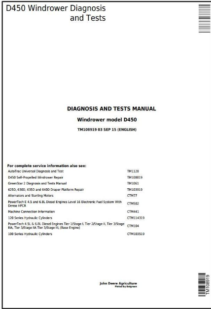
John Deere D450 Self-Propelled Hay and Forage Windrower Diagnostic & Tests Service Manual PDF (TM108919) - MJODTM108919.zip
The Complete Diagnostics & Tests service guide for the John Deere Self-Propelled Hay and Forage Windrower Model D450 comes with electrical wiring schematics and shop-level details, letting you maintain, troubleshoot, and repair your machine just like a trained technician.
Inside the Diagnosis and Tests Service Manual for the John Deere Self-Propelled Hay and Forage Windrower Model D450, you'll find:
* Numbered table of contents easy to use so that you can find the information you need fast.
* Detailed sub-steps expand on repair procedure information
* Numbered instructions guide you through every repair procedure step by step.
* Troubleshooting and electrical service procedures are combined with detailed wiring diagrams for ease of use.
* Notes, cautions and warnings throughout each chapter pinpoint critical information.
* Bold figure number help you quickly match illustrations with instructions.
* Detailed illustrations, drawings and photos guide you through every procedure.
* Enlarged inset helps you identify and examine parts in detail.
TM108919 - John Deere Self-Propelled Hay and Forage Windrowers Models D450 Technical Manual (Diagnosis & Tests).PDF
Total Pages: 3,331 pages
File Format: PDF (bookmarked, ToC, Searchable, Printable, high quality)
Language: English
MAIN SECTIONS
Diagnostics Trouble Codes
CAB - Cab Control Unit - Diagnostic Trouble Codes
OOC - Out of Cab Control Unit - Diagnostic Trouble Codes
MHC - Multi-function Lever - Diagnostic Trouble Codes
ADU - Armrest Display Unit - Diagnostic Trouble Codes
Engine
Air Intake and Cooling
Electrical
Accessing Diagnostic Codes and Addresses
Diagnostic Addresses by Controller
Machine Setting Addresses
Diagnostic Trouble Codes, Warning Messages, and Fault Codes
Calibration Procedures
Air Seat
Auxiliary Power
CAN Bus
Control Unit - CAB/CPM
Control Unit - OOC/OPM
Control Unit - ECU
Control Unit - ADU
Control Unit - PDU
Engine and Fuel Controls
GreenStar - Diagnostic
Heating, Ventilating, and Air Conditioning
Horn
Lighting - Diagnostic
Park Brake
Platform
- Belt Speed
- Engage/Disengage
- Float Pressure
- Header Height
- Raise/Lower
- Reel Fore/Aft
- Reel Raise/Lower
- Reel Speed
- Reel Reverse
- Tilt
Power Distribution - Diagnostic
Power Mirrors
Primary Display Unit
- Area Counter
- Engine Air Filter Monitoring
- Engine/Header Hours
- Engine Oil Pressure Monitoring
- Engine Speed Monitoring
- Engine Temperature Monitoring
- Fuel Level Monitoring
- Ground Speed Sensors
- Hydraulic Oil Filter Monitoring
- Hydraulic Oil Temperature Monitoring
- Hydrostatic Charge Pressure Monitoring
- Operator Presence
- Water in Fuel Monitoring
Radio
Range Shift
Rear Assist Steering
Rotating Wand
Starting and Charging
Throttle
Windshield Wiper/Washer
Connector Information (end views, numbers, location photos)
Power Train
Hydrostatic Drive
Range Shift
Hydrostatic Steering and Park Brake Release
Final Drive
Component Identification and Location
Brakes
Hydraulics
Charge Pump
Platform
- Auger Drive
- Belt Drive
- Cutterbar Tilt
- Drive System
- Frame Float
- Raise/Lower
- Reel Drive
- Reel Fore/Aft
- Reel Raise/Lower
Steering
Operator Station
tm108919 - D450 Windrower Diagnosis and Tests
Table of Contents
Foreword
Section 210: Safety Information
Group 05: General Safety
Service Technician Response
Recognize Safety Information
Understand Signal Words
Follow Safety Instructions
Handle Fluids Safely—Avoid Fires
Handling Batteries Safely
Prevent Battery Explosions
Prepare for Emergencies
Prevent Acid Burns
Handle Chemical Products Safely
Avoid High-Pressure Fluids
Stay Clear of Rotating Drivelines
Park Windrower Safely
Stay Clear of Rotating Driveline
Support Machine Properly
Wear Protective Clothing
Work in Clean Area
Service Machines Safely
Service Accumulator Systems Safely
Work In Ventilated Area
Illuminate Work Area Safely
Replace Safety Signs
Use Proper Lifting Equipment
Service Tires Safely
Remove Paint Before Welding or Heating
Avoid Heating Near Pressurized Fluid Lines
Avoid Harmful Asbestos Dust
Use Proper Tools
Decommissioning — Proper Recycling and Disposal of Fluids and Components
Practice Safe Maintenance
Live With Safety
Use Adequate Service Facilities
Practice Safe Service Procedures
Section 211: Diagnostic Trouble Codes
Group 1: CAB — Cab Control Unit — Diagnostic Trouble Codes
CAB 000096.01 - Low Fuel Level
CAB 000167.03 - The alternator charging system is greater than 16.0 VDC. Alternator issue.
CAB 000167.04 - The alternator charging system is putting out less than 12.5 VDC for 60 seconds. Alternator issue.
CAB 000168.01 - System voltage is too low with the engine not running.
CAB 000168.04 - Battery voltage is less than 9.0 VDC
CAB 000170.03 - Cab air temperature sensor output (cc# 766) is out of range - greater than 4.93 VDC
CAB 000170.04 - Cab air temperature sensor (cc# 766) is out of range - less than 0.10 VDC
CAB 000171.03 - Cab inlet air temperature sensor output (cc# 763) is out of range - greater than 4.93 VDC
CAB 000171.04 - Cab inlet air temperature sensor output (cc# 763) is out of range - less than 0.10 VDC
CAB 000444.04 - Battery 2 voltage is less than 9.0 VDC
CAB 000629.12 - Control unit CAB has reset itself due to watchdog timer
CAB 000639.12 - CAN Bus message 1 is not arriving on time or missing
CAB 000639.14 - No CAN Bus 1 messages are arriving
CAB 000677.03 - Start relay signal (cc# 107) is ON when commanded OFF by control unit CAB
CAB 000677.06 - Start relay signal (cc# 107) is OFF when commanded ON by control unit CAB
CAB 000875.04 - Air conditioning low pressure switch is open
CAB 001231.09 - No local CAN Bus messages are arriving
CAB 001231.12 - Local CAN Bus message is not arriving on time or missing
CAB 001231.14 - No local CAN Bus messages are arriving
CAB 001232.09 - MHC control unit communication fault
CAB 001491.03 - Cab backlighting (cc# 511) is ON when commanded OFF by control unit CAB
CAB 001491.06 - Cab backlighting (cc# 511) is OFF when commanded ON by control unit CAB
CAB 001503.03 - A row of switches in the armrest switch matrix is shorted to voltage
CAB 001503.04 - A row of switches in the armrest switch matrix is shorted to ground
CAB 001503.05 - Armrest matrix connection status (cc# 928) voltage too low
CAB 001503.11 - A column of switches in the armrest switch matrix is shorted to ground
CAB 001504.04 - Seat switch has remained closed for eight continuous hours of operation
CAB 001504.14 - Seat switch is not closed
CAB 001544.03 - A row of switches in the multifunction control handle is shorted to voltage
CAB 001544.11 - A column of switches in the multifunction control handle is shorted to ground
CAB 001547.03 - Core temperature sensor output (cc# 754) is out of range - greater than 4.93 VDC
CAB 001547.04 - Core temperature sensor output (cc# 754) is of out of range - less than 0.10 VDC
CAB 001549.03 - Temperature door position (cc# 774) is out of range - greater than 4.5 VDC
CAB 001549.04 - Temperature door position (cc# 774) is out of range - less than 0.2 VDC
CAB 001549.06 - Temperature door actuator high (cc# 771) is OFF when commanded ON by control unit CAB
CAB 001549.12 - Temperature door has not completed the movement requested by the control unit CAB
CAB 001549.13 - Temperature door has not been calibrated
CAB 001675.31 - The following conditions occurred: 0=No Faults, 1=A fault detected on the driver, 2=Platform engage switch engaged forward
CAB 001865.11 - One of the following conditions occurred: Key switch run (cc# 013) is ON when key switch accessory (cc# 011) and key switch start (cc# 104) is OFF, Key switch start (cc# 104) is ON when key switch run (cc# 013) is OFF, Key switch start (cc# 104) is ON when key switch accessory (cc# 011) is ON
CAB 002372.03 - Left rear brake light (cc# 525) is ON when commanded OFF by control unit CAB
CAB 002372.04 - Left rear brake light (cc# 525) is OFF when commanded ON by control unit CAB
CAB 002372.05 - Left rear brake light (cc# 525) is open circuit
CAB 002372.12 - Left rear brake light (cc# 525) is failed
CAB 002374.03 - Right rear brake light (cc# 524) is ON when commanded OFF by control unit CAB
CAB 002374.04 - Right rear brake light (cc# 524) is OFF when commanded ON by control unit CAB
CAB 002374.05 - Right rear brake light (cc# 524) is open circuit
CAB 002374.12 - Right rear brake light (cc# 524) is failed
CAB 002876.11 - Right turn signal (cc# 513) and left turn signal (cc# 514) are ON the same time
CAB 003509.03 - Control unit CAB sensor supply 1 (cc# 233) is out of range - greater than 5.5 VDC
CAB 003509.04 - Control unit CAB sensor supply 1 (cc# 233) is out of range - less than 4.5 VDC
CAB 003510.03 - Control unit CAB sensor supply 2 (cc# 243) is out of range - greater than 5.5 VDC
CAB 003510.04 - Control unit CAB sensor supply 2 (cc# 243) is out of range - less than 4.5 VDC
CAB 003597.06 - CAB PTC power (cc# 552) is out of range - less than 4.0 VDC
CAB 520604.03 - Road lights enabled indicator (cc# 519) has voltage present when control unit CAB has turned low side driver ON
CAB 520604.06 - Road lights enabled indicator (cc# 519) has no voltage present when control unit CAB has turned low side driver OFF
CAB 520607.03 - Field lights enabled indicator (cc# 536) has voltage present when control unit CAB has turned low side driver ON
CAB 520607.06 - Field lights enabled indicator (cc# 536) has no voltage present when control unit CAB has turned low side driver OFF
CAB 520608.03 - Reel reverse enabled indicator (cc# 533) is ON when commanded OFF by control unit CAB
CAB 520608.06 - Reel reverse enabled indicator (cc# 533) when commanded ON by control unit CAB
CAB 520610.03 - Low speed gear enabled indicator (cc# 538) has voltage present when control unit CAB has turned low side driver ON
CAB 520610.06 - Low speed gear enabled indicator (cc# 538) has no voltage present when control unit CAB has turned low side driver OFF
CAB 520611.03 - High speed fear enabled indicator (cc# 539) has voltage present when control unit CAB has turned low side drive ON
CAB 520611.06 - High speed gear enabled indicator (cc# 539) has no voltage present when control unit CAB has turned low side driver OFF
CAB 520612.03 - Work lights enabled indicator (cc# 521) has voltage present when control unit CAB has turned low side driver ON
CAB 520612.06 - Work lights enabled indicator (cc# 521) has no voltage present when control unit CAB has turned low side driver OFF
CAB 520619.03 - ATC enabled indicator (cc# 534) has voltage present when control unit CAB has turned low side driver ON
CAB 520619.06 - ATC enabled indicator (cc# 534) has no voltage present when control unit CAB has turned off low side driver
CAB 520620.03 - A/C and defog enabled indicator (cc# 541) has voltage present when control unit CAB has turned low side driver ON
CAB 520620.06 - A/C and defog enabled indicator (cc# 541) has no voltage present when control unit CAB has turned low side driver OFF
CAB 520870.31 - EEPROM Banking - write/read data in the Zone 1 failed due to checksum failure
CAB 520871.31 - EEPROM Banking - write/read data in the Zone 2 failed due to checksum failure
CAB 520872.31 - EEPROM Banking - write/read data in the Zone 3 failed due to checksum failure
CAB 520873.31 - EEPROM Banking - write/read data in the Zone 4 failed due to checksum failure
CAB 520874.31 - EEPROM Banking - write/read data in the Zone 5 failed due to checksum failure
CAB 520875.31 - EEPROM Banking - write/read data in the Zone 6 failed due to checksum failure
CAB 520876.31 - EEPROM Banking - write/read data in the Zone 7 failed due to checksum failure
CAB 520892.31 - EEPROM Banking - write/read data in the Copy Zone 1 failed due to checksum failure
CAB 520893.31 EEPROM Banking - write/read data in the Copy Zone 2 failed due to checksum failure -
CAB 520894.31 - EEPROM Banking - write/read data in the Copy Zone 3 failed due to checksum failure
CAB 520895.31 - EEPROM Banking - write/read data in the Copy Zone 4 failed due to checksum failure
CAB 520896.31 - EEPROM Banking - write/read data in the Copy Zone 5 failed due to checksum failure
CAB 520897.31 - EEPROM Banking - write/read data in the Copy Zone 6 failed due to checksum failure
CAB 521071.01 - Steering linkage not centered
CAB 521071.04 - Steering linkage not centered
CAB 522019.03 - CPM micro power (cc# 012) is ON when commanded OFF by control unit CAB
CAB 522019.04 - CPM micro power (cc# 012) is OFF when commanded ON by control unit CAB
CAB 522053.03 - HVAC compressor clutch (cc# 941) is ON when commanded OFF by control unit CAB
CAB 522053.05 - HVAC compressor clutch (cc# 941) is open circuit
CAB 522053.06 - HVAC compressor clutch (cc# 941) is OFF when commanded ON by control unit CAB
CAB 522058.03 - Cab roof lights 3, 4 high (cc# 584) is ON when commanded OFF by control unit CAB
CAB 522058.05 - Cab roof lights 3, 4 high (cc# 584) is open circuit
CAB 522058.06 - Cab roof lights 3, 4 high (cc# 584) is OFF when commanded ON by control unit CAB
CAB 522132.01 - The engine is not at harvesting speed
CAB 522139.01 - Float pressure is too low
CAB 523319.03 - CAB switched power (cc# 932) is ON when commanded OFF by control unit CAB
CAB 523319.06 - CAB switched power (cc# 932) is OFF when commanded ON by control unit CAB
CAB 523490.03 - High idle indicator (cc# 529) has voltage present when control unit CAB has turned low side driver ON
CAB 523490.06 - High idle indicator (cc# 529) has no voltage present when control unit CAB has turned low side driver OFF
CAB 523491.03 - Variable idle indicator (cc# 528) has voltage present when control unit CAB has turned low side driver ON
CAB 523491.06 - Variable idle indicator (cc# 528) has no voltage present when control unit CAB has turned low side driver OFF
CAB 523492.03 - Low idle indicator (cc# 527) has voltage present when control unit CAB has turned low side driver ON
CAB 523492.06 - Low idle indicator (cc# 527) has no voltage present when control unit CAB has turned low side driver OFF
CAB 523622.04 - CPM power 5 (cc# 062) less than 10.5 VDC at the CPM input
CAB 523623.03 - Switched auxiliary power 1 (cc# 071) is ON when commanded OFF by control unit CAB
CAB 523623.06 - Switched auxiliary power 1 (cc# 071) is OFF when commanded ON by control unit CAB
CAB 523629.03 - Left amber lights (cc# 516) are ON when commanded OFF by control unit CAB
CAB 523629.05 - Left amber lights (cc# 516) are open circuit
CAB 523629.06 - Left amber lights (cc# 516) are OFF when commanded ON by control unit CAB
CAB 523629.12 - Left amber light (cc# 516) is failed
CAB 523630.03 - Cab roof lights 1, 6 (cc# 581) is ON when commanded OFF by control unit CAB
CAB 523630.05 - Cab roof lights 1, 6 (cc# 581) is open circuit
CAB 523630.06 - Cab roof lights 1, 6 (cc# 581) is OFF when commanded ON by control unit CAB
CAB 523631.05 - Recirculation fan power (cc# 082) is open circuit
CAB 523631.06 - Recirculation fan power (cc# 082) is OFF when commanded ON by control unit CAB
CAB 523632.03 - Cab roof lights 2, 5 (cc# 583) is ON when commanded OFF by control unit CAB
CAB 523632.05 - Cab roof lights 2, 5 (cc# 583) is open circuit
CAB 523632.06 - Cab roof lights 2, 5 (cc# 583) is OFF when commanded ON by control unit CAB
CAB 523633.03 - Right amber lights (cc# 515) are ON when commanded OFF by control unit CAB
CAB 523633.05 - Right amber lights (cc# 515) are open circuit
CAB 523633.06 - Right amber lights (cc# 515) are OFF when commanded ON by control unit CAB
CAB 523633.12 - Right amber light (cc# 515) is failed
CAB 523639.03 - Rear red tail lights (cc# 515) are ON when commanded OFF by control unit OOC
CAB 523639.05 - Rear red tail lights (cc# 515) are open circuit
CAB 523639.06 - Rear red tail lights (cc# 506) are OFF when commanded ON by control unit OOC
CAB 523639.12 - Rear red tail lights (cc# 506) failed
CAB 523645.11 - One of the following conditions occurred: Header engage switch (cc# 988) is ON when both header forward switch (cc# 987) and header reverse switch (cc# 989) are OFF, Header engage switch (cc# 988) is ON, Header engage switch (cc# 988) is ON when both header forward switch (cc# 987) and header reverse switch (cc# 989) are ON.
CAB 523646.03 - Outlet air temperature sensor output (cc# 791) is out of range - greater than 4.93 VDC
CAB 523646.04 - Outlet air temperature sensor output (cc# 761) is out of range - less than 0.10 VDC
CAB 523647.03 - Temperature door actuator high (cc# 771) and/or temperature door actuator low (cc# 773) is ON when commanded OFF by control unit CAB
CAB 523647.06 - Temperature door actuator low (cc# 773) is OFF when commanded ON by control unit CAB
CAB 523648.04 - CPM power 4 (cc# 052) less than 10.5 VDC at the CPM input
CAB 523649.04 - CPM power 3 (cc# 042) less than 10.5 VDC at the CPM input
CAB 523650.04 - CPM power 2 (cc# 032) less than 10.5 VDC at the CPM input
CAB 523653.04 - CPM power 1 (cc# 022) less than 10.5 VDC at the CPM input
CAB 523668.03 - Function active indicator (cc# 537) has voltage present when control unit CAB has turned low side driver ON
CAB 523668.06 - Function active indicator (cc# 537) has no voltage present when control unit CAB has turned low side driver OFF
CAB 523672.03 - Pressurizer fan motor (cc# 921) is ON when commanded OFF by control unit CAB
CAB 523672.05 - Pressurizer fan motor (cc# 921) is open circuit
CAB 523672.06 - Pressurizer fan motor (cc# 921) is OFF when commanded ON by control unit CAB
CAB 523746.04 - During start-up, key switch run signal (cc# 013) is ON but system wakeup power (cc# 006) is OFF before commanded ON by control unit CAB
CAB 523746.06 - System wakeup power (cc# 006) is OFF when commanded ON by control unit CAB
Group 2: OOC — Out of Cab Control Unit — Diagnostic Trouble Codes
OOC 000629.12 - Control unit OOC has reset itself due to watchdog timer
OOC 000639.14 - No CAN Bus 1 messages are arriving
OOC 000639.12 - CAN Bus 1 message is not arriving on time or missing
OOC 001231.09 - Local CAN Bus message is not arriving on time or missing
OOC 001231.14 - No local CAN Bus messages are arriving
OOC 001231.12 - Local CAN Bus message is not arriving on time or missing
OOC 001515.13 - Header is detected but the header calibration has not been performed
OOC 001517.03 - Header lift cylinder pressure sensor (cc# 704) is out of range - greater than 4.93 VDC
OOC 001517.04 - Header lift cylinder pressure sensor (cc# 704) is out of range - less than 0.25 VDC
OOC 001519.03 - Header raise solenoid (cc# 427) is ON when commanded OFF by control unit OOC
OOC 001519.04 - Header raise solenoid (cc# 427) is OFF when commanded ON by control unit OOC
OOC 001519.05 - Header raise solenoid (cc# 427) is open circuit
OOC 001519.06 - Header raise solenoid (cc#427) is over current
OOC 001519.12 - Driver for header raise solenoid (cc# 427) is faulty
OOC 001519.13 - Platform lift speed calibration has not been performed
OOC 001520.03 - Header lower solenoid (cc# 407) is ON when commanded OFF by control unit OOC
OOC 001520.04 - Header lower solenoid (cc# 407) is OFF when commanded ON by control unit OOC
OOC 001520.05 - Header lower solenoid (cc# 407) is open circuit
OOC 001520.06 - Header lower solenoid (cc# 407) is over current
OOC 001520.12 - Driver for header lower solenoid (cc# 407) is faulty