
John Deere 9470RT 9520RT 9570RT 9RT Track Tractor Workshop Repair Service Manual PDF (TM119719) - MJODTM119719.zip
A full workshop service and repair manual for John Deere 9470RT, 9520RT, and 9570RT Tractors (S.N. 906000—), offering dealer-level guidance to keep, fix, and overhaul these machines the way trained technicians do.
The John Deere 9470RT, 9520RT, and 9570RT Tractor repair manual (workshop edition) covers:
* Numbered table of contents easy to use so that you can find the information you need fast.
* Detailed sub-steps expand on repair procedure information
* Numbered instructions guide you through every repair procedure step by step.
* Notes, cautions and warnings throughout each chapter pinpoint critical information.
* Bold figure number help you quickly match illustrations with instructions.
* Detailed illustrations, drawings and photos guide you through every procedure.
* Enlarged inset helps you identify and examine parts in detail.
tm119719 - 9RT Tractors Repair(S. N. 906000—916999) Technical Manual.pdf
tm119728 - Remise en état des tracteurs 9RT (N° de série 906000—916999).pdf
Total Pages: 1,731 pages
File Format: PDF/EPUB/MOBI/AZW (PC/Mac/Android/Kindle/iPhone/iPad; bookmarked, ToC, Searchable, Printable)
Category: Repair
Language: English French
Published on 2019/06/26
MAIN SECTIONS
Foreword
Dealer Predelivery Information Form
General Information
Safety
General Information
Engine
Component Removal and Installation
Engine Repair
Fuel, Air Intake, Exhaust, and Cooling
Diesel Fuel System
Air Intake System
Auxiliary Drive System
Radiator and Coolers
Exhaust System
Electrical
Connectors
Charging Circuit
Starting Circuit
Relays, Fuses, Solenoids, and Switches
Monitoring Systems and Sensors
CommandARM™
Implement and Accessory Connectors
Convenience and Accessory
PowerShift Transmission (PST)
Component Removal and Installation
In Tractor Repair
Transmission Repair
Assemble Transmission
Drive Train
Component Removal and Installation
Drive Shafts
PTO Clutch
PTO Clutch Valve
PTO Drop Box
Rear Axle Assembly
Component Removal and Installation
Outboard Planetary Final Drive
Outboard Planetary Service Brakes
Wheel Hub and Axle Housing
Steering Differential Carrier
Differential Case Steering Gears
Input Pinion Housing
Differential Case Drive Gears
Brakes
Service Brakes
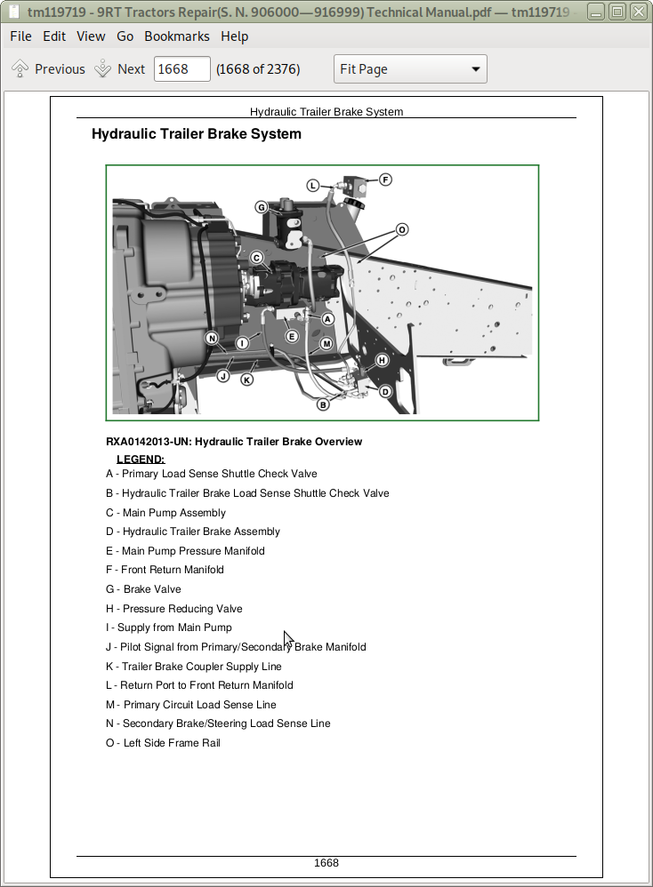
Hydraulic Trailer Brake
Steering
Steering Column
Steering Wheel Position Input Assembly
Steering Pump
Steering Pump Drive Gear Case
Steering Motor
Hydraulics
Component Removal and Installation
Hydraulic System Repair
Hydraulic Pump
Gear Pump Assembly
Filter Housings and Control Valves
Hitch Valve, Selective Control Valves, and Couplers
Rear Hitch
Miscellaneous
Hood and Side Panels
Platform Step Assembly
Hitch Frame and Drawbar
Track Frame and Components
Track
Tension Cylinder and Accumulator
Track Frame
Track Suspension
Cab and Open Operator’s Station
Component Removal and Installation
Heating, Ventilating, and Air Conditioning (HVAC)
ComfortCommand™ Seat
Cab Door and Windshield
Dealer Tools
Dealer Fabricated Tools
tm119719 - 9RT Tractors Repair(S. N. 906000—916999)
Table of Contents
Foreword
Dealer Predelivery Information Form
Section 10: General Information
Group 05A: Safety
Recognize Safety Information
Understand Signal Words
Follow Safety Instructions
Wear Protective Clothing
Service Machines Safely
Stay Clear of Rotating Drivelines
Handle Fluids Safely—Avoid Fires
Prevent Battery Explosions
Prepare for Emergencies
Remove Paint Before Welding or Heating
Avoid Heating Near Pressurized Fluid Lines
Handle Starting Fluid Safely
In Case of Fire
Avoid Static Electricity Risk When Refueling
Avoid Hot Exhaust
Clean Exhaust Filter Safely
Prevent Acid Burns
Handle Agricultural Chemicals Safely
Clean Vehicle of Hazardous Pesticides
Handling Batteries Safely
Avoid Harmful Asbestos Dust
Decommissioning — Proper Recycling and Disposal of Fluids and Components
Avoid High-Pressure Fluids
Wait Before Opening High-Pressure Fuel System
Service Accumulator Systems Safely
Protect Against High Pressure Spray
Service Cooling System Safely
Prevent Machine Runaway
Avoid Backover Accidents
Keep ROPS Installed Properly
Park Machine Safely
Support Machine Properly
Work in Clean Area
Work In Ventilated Area
Illuminate Work Area Safely
Use Proper Lifting Equipment
Instructional Seat
Use Steps and Handholds Correctly
Transport Tractor Safely
Practice Safe Maintenance
Use Proper Tools
Construct Dealer-Made Tools Safely
Replace Safety Signs
Install All Guards
Live With Safety
Group 05B: General Information
List of References
Trademarks
Sealants and Adhesives Cross-Reference Chart
Metric Bolt and Screw Torque Values
Unified Inch Bolt and Screw Torque Values
Face Seal Fittings Assembly and Installation—All Pressure Applications
Metric Face Seal And O-Ring Stud End Fitting Torque Chart—Standard Pressures
Metric Face Seal and O-Ring Stud End Fitting Torque Chart—High Pressure Applications
SAE Face Seal and O-Ring Stud End Fitting Torque Chart—Standard Pressures
SAE Face Seal and O-Ring Stud End Fitting Torque Chart—High Pressure Applications
Four Bolt Flange Fittings Assembly and Installation—All Pressure Applications
SAE Four Bolt Flange Cap Screw Torque Values—Standard Pressure Applications
SAE Four Bolt Flange Cap Screw Torque Values—High Pressure Applications
External Hexagon Port Plug Torque Chart
Prevent Hydraulic System Contamination
Check Oil Lines and Fittings
Basic Electrical Component Handling / Precautions For Vehicles Equipped With Computer Controlled Systems
Identify Zinc-Flake Coated Fasteners
Use Torque Wrench Adapter
Servicing and Connecting Snap to Connect STC® Fittings
Use Special Wrench
Install Hydraulic Fittings
Remove and Install Rivet Nut Fasteners
Selective Catalytic Reduction (SCR) System Overview
Restored Operation Option
Aftertreatment Indicators Overview
Cleaning Diesel Exhaust Fluid (DEF) Tank
Changing Diesel Exhaust Fluid (DEF) Dosing Unit Filter
Section 20: Engine
Group 00: Component Removal and Installation
List of References
Essential, Recommended, and Fabricated Tools 20—00
Specifications 20—00
Remove Engine—13.5 L
Install Engine—13.5 L
Remove Engine—15 L
Install Engine—15 L
Remove and Install Engine Oil Pan
Remove and Install Front Support
Group 05: Engine Repair
List of References
Specifications 20—05
Repair Engine—Use CTM
Replace Torsional Damper
Section 30: Fuel, Air Intake, Exhaust, and Cooling
Group 05: Diesel Fuel System
List of References
Essential, Recommended, and Fabricated Tools 30—05
Specifications 30—05
Fuel Tank Components
Remove and Install Left-Hand Fuel Tank
Remove and Install Right-Hand Fuel Tank
Remove and Install Center Fuel Tank
Replace Fuel Filter, Fuel Pump, and Bleed Fuel System
Group 10: Air Intake System
List of References
Specifications 30—10
Air Intake Pipe Connections
Remove and Install Intake Housing—13.5 L
Remove and Install Intake Housing—15 L
Remove and Install Aspirator Hose—13.5 L
Remove and Install Aspirator Hose—15 L
Remove and Install Charge Air Cooler Pipes—13.5 L
Remove and Install Charge Air Cooler Pipes—15 L
Group 15: Auxiliary Drive System
List of References
Essential, Recommended, and Fabricated Tools 30—15
Other Material 30—15
Specifications 30—15
Inspect Belt Tensioner
Drive Belt Routings
Remove and Install Vari-Cool™ Fan Belt—13.5 L
Remove and Install Vari-Cool™ Drive Assembly—13.5 L
Remove and Install Vari-Cool™ Fan Driven Assembly—13.5 L
Repair Vari-Cool™ Drive Assembly—13.5 L
Repair Vari-Cool™ Fan Driven Assembly—13.5 L
Check and Fill Vari-Cool™ Fan Sheaves—13.5 L
Remove and Install Vari-Cool™ Control Valve—13.5 L
Repair Vari-Cool™ Control Valve—13.5 L
Remove and Install Hydraulic Fan Pump—15 L
Remove and Install Hydraulic Fan Motor—15 L
Repair Hydraulic Fan Pump—15 L
Repair Hydraulic Fan Motor—15 L
Group 20: Radiator and Coolers
List of References
Essential, Recommended, and Fabricated Tools 30—20
Specifications 30—20
Other Material 30—20
Draining, Flushing, and Refilling Cooling System—13.5 L
Draining, Flushing, and Refilling Cooling System—15 L
Test Radiator and Deaeration Tank
Test Deaeration Cap
Remove and Install Deaeration Tank
Remove and Install Radiator—13.5 L
Remove and Install Radiator—15 L
Remove and Install Charge Air Cooler—13.5 L
Remove and Install Charge Air Cooler—15 L
Remove and Install Hydraulic Oil and Fuel Cooler—13.5 L
Remove and Install Hydraulic Oil Cooler—15 L
Remove and Install Fuel Cooler—15 L
Remove and Install Air Conditioner Condenser—13.5 L
Remove and Install Air Conditioner Condenser—15 L
Leak Test Hydraulic Oil Cooler
Group 25: Exhaust System
List of References
Other Material 30—25
Specifications 30—25
Service Exhaust System
Replace NOx Sensor
Drain DEF Tank
Remove and Install DEF Tank
Replace Header Assembly
Replace DEF Dosing Unit
Replace DEF Dosing Injector
Section 40: Electrical
Group 05: Connectors
List of References
Essential, Recommended, and Fabricated Tools 40—05
Other Material 40—05
Use Electrical Insulating Compound
Using High-Pressure Washers
Installation of Repair Wire Assembly
Repair AMP™ Connector
Repair AMPSEAL 16™ Connectors
Bosch™ Connectors
Remove Connector Body from Blade Terminals
CINCH™ Control Unit Connectors
Exploded View—CINCH™ FlexBox Connectors
CINCH™ FlexBox Connectors
Repair CPC™ Blade Type Connectors
Repair CPC™, Large Mate-N-Loc™, and Metrimate™ Pin Type Connectors
Repair DEUTSCH™ Connectors
Repair DEUTSCH™ Implement Connectors
Repair ITT Connector
Repair Small Mate-N-Loc™ Socket Connector
Repair Small Mate-N-Loc™ Pin Connector
Repair (Pull Type) Metri-Pack™ Connectors
Repair (Push Type) Metri-Pack™ Connectors
Repair Molex™ Control Unit Connectors
Repair Molex™ Connector
Repair SUMITOMO™ Connectors
Repair Tyco™ Fuel Injector Connector
Repair WEATHER PACK™ Connector
Repair YAZAKI™ Connectors
Group 10: Charging Circuit
List of References
Specifications 40—10
Disconnect Electrical Circuit
Repair Alternator—Use CTM
Replace Alternator
Replace Alternator and Battery Fuse
Replace Alternator and Battery Relay
Replace Batteries
Group 15: Starting Circuit
List of References