
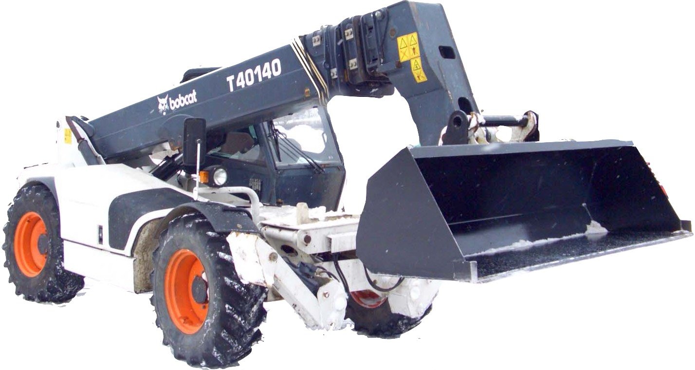
Bobcat T40140 T40170 T40180 Telescopic Handler Workshop Repair Service Manual PDF - MBOBT40140.zip
A full workshop-level service manual featuring electrical wiring schematics for the Bobcat T40140, T40170, and T40180 Telescopic Handlers, packed with the technical data needed to service, troubleshoot, and fix these machines the way trained technicians do.
Inside the Bobcat T40140-T40170-T40180 service and repair manual, you'll find:
* Numbered table of contents easy to use so that you can find the information you need fast.
* Detailed sub-steps expand on repair procedure information
* Numbered instructions guide you through every repair procedure step by step.
* Troubleshooting and electrical service procedures are combined with detailed wiring diagrams for ease of use.
* Notes, cautions and warnings throughout each chapter pinpoint critical information.
* Bold figure number help you quickly match illustrations with instructions.
* Detailed illustrations, drawings and photos guide you through every procedure.
* Enlarged inset helps you identify and examine parts in detail.
4852040 (8-03) - T40140, T40170 V2 Boom Service Manual.pdf
4852040 (10-12) - T40140, T40170 V2 Boom Service Manual.pdf
4950145 (08-08) - T40140-T40170 Service Manual.pdf
6986768 (2-10) - T40140, T40170 Telescopic Handler Service Manual.pdf
6986768 (08-08) Revised (08-12) - T40140, T40170 Telescopic Handler Service Manual.pdf
6989561 (2-10) - T40140 Telescopic Handler Operation & Maintenance Manual.pdf
6989562 (2-10) - T40170 Telescopic Handler Operation & Maintenance Manual.pdf
6990783 (07-14) - T40140, T40180 Telescopic Handler Service Manual.pdf
6990786 (07-14) - T40140, T40180 Telescopic Handler Service Manual.pdf
Pages: 4,183
File Format: PDF
Language: English
MAIN SECTIONS
SAFETY AND MAINTENANCE . . 10-01
HYDRAULIC SYSTEM . . 20-01
HYDROSTATIC SYSTEM . . 30-01
DRIVE SYSTEM . . 40-01
MAINFRAME . . 50-01
ELECTRICAL SYSTEM & ANALYSIS . . 60-01
ENGINE SERVICE . . 70-01
HEATING, VENTILATION, AIR CONDITIONING . . 80-01
SPECIFICATIONS . . SPEC-01
ALPHABETICAL INDEX . .INDEX-01
4852040 (10-12) - T40140, T40170 V2 Boom Service Manual.......1
CONTENTS.......2
NEW BOOM.......3
Introduction.......4
Stronger boom.......4
Material.......4
Counter jib.......4
New boom design.......5
Different components of the boom.......5
Front part of element 1.......5
Front part of element 2.......5
Rear part of element 2.......6
Front part of element 3.......6
Rear part of element 3.......7
Rear part of element 4.......7
Telescoping cylinder.......8
Cassette........8
Pads.......9
New concept.......9
Lubricator built into the pads.......9
Glide angle iron for the pads.......9
Compensation cylinder.......10
Mechanical kinematics of the boom.......10
Tensioner for lower chains.......10
Hooking up the chains.......11
Hydraulic kinematics of the boom.......11
Electric enclosure.......12
Feature of the T40170.......12
Attachments.......12
SPECIFIC PROCEDURES - V2 BOOM.......13
Safety.......14
Removal and installation of the chains/hoses cassette.......14
Removal.......14
Installation.......15
Removal and installation of boom elements.......15
Remove elements 2 and 3 (T40140) or 2, 3 and 4 (T40170).......15
Checking the tension of the telescoping chains.......17
Checking the wear of the telescoping chains.......17
Adjusting the extension and retraction chains.......18
Tools needed.......18
First.......18
Retraction chains.......18
Extension chains.......18
Replacing the boom retraction or extension chains.......19
General views.......19
Work on rear of boom.......20
Work on front of boom.......20
Replacing boom pads.......20
Parts.......20
Front pads of the elements.......21
Removing.......21
Installation.......21
Rear pads of the elements.......22
Removing.......22
Installation.......22
Important reminder.......23
Removal and installation of the compensation cylinder.......23
Removal.......23
Installation.......24
Removal and installation of the tilt cylinder.......25
Removal.......25
Installation.......25
Removal and installation of the lift cylinder.......26
Removal.......26
Installation.......27
Removal and installation of the telescoping cylinder.......27
Removal.......27
Installation.......28
T40140 SPECIFICATIONS.......29
Introduction.......30
Detailed specifications.......30
General.......30
Hydrostatic Transmission.......30
Cycle time.......31
Load Charts.......31
T40140 on stabilisers.......31
T40140 on tyres.......32
Platform load charts.......32
Load Chart 1.......32
Load Chart 2.......33
Load Chart 3.......33
Load Chart 4.......34
Self leveling and side shift of the load.......34
Dimensions.......35
T40170 SPECIFICATIONS.......37
Introduction.......38
Detailed specifications.......38
General.......38
Hydrostatic Transmission.......38
Cycle time.......39
Load Charts.......39
T40170 on stabilisers.......39
T40170 on tyres.......40
Platform load charts.......40
Load Chart 1.......40
Load Chart 2.......41
Load Chart 3.......41
Load Chart 4.......42
Self leveling and side shift of the load.......42
Dimensions.......43
SERVICE MANUAL REVISION.......45
Revision No: T40140, T40170 - 1.......45
4852040 (8-03) - T40140, T40170 V2 Boom Service Manual.......47
CONTENTS.......48
NEW BOOM.......49
Introduction.......50
Stronger boom.......50
Material.......50
Counter jib.......50
New boom design.......51
Different components of the boom.......51
Front part of element 1.......51
Front part of element 2.......51
Rear part of element 2.......52
Front part of element 3.......52
Rear part of element 3.......53
Rear part of element 4.......53
Telescoping cylinder.......54
Cassette........54
Pads.......55
New concept.......55
Lubricator built into the pads.......55
Glide angle iron for the pads.......55
Compensation cylinder.......56
Mechanical kinematics of the boom.......56
Tensioner for lower chains.......56
Hooking up the chains.......57
Hydraulic kinematics of the boom.......57
Electric enclosure.......58
Feature of the T40170.......58
Attachments.......58
SPECIFIC PROCEDURES - V2 BOOM.......59
Safety.......60
Removal and installation of the chains/hoses cassette.......60
Removal.......60
Installation.......61
Removal and installation of boom elements.......61
Remove elements 2 and 3 (T40140) or 2, 3 and 4 (T40170).......61
Checking the tension of the telescoping chains.......63
Checking the wear of the telescoping chains.......63
Adjusting the extension and retraction chains.......64
Tools needed.......64
First.......64
Retraction chains.......64
Extension chains.......64
Replacing the boom retraction or extension chains.......65
General views.......65
Work on rear of boom.......66
Work on front of boom.......66
Replacing boom pads.......66
Parts.......66
Front pads of the elements.......67
Removing.......67
Installation.......67
Rear pads of the elements.......68
Removing.......68
Installation.......68
Important reminder.......69
Removal and installation of the compensation cylinder.......69
Removal.......69
Installation.......70
Removal and installation of the tilt cylinder.......71
Removal.......71
Installation.......71
Removal and installation of the lift cylinder.......72
Removal.......72
Installation.......73
Removal and installation of the telescoping cylinder.......73
Removal.......73
Installation.......74
T40140 SPECIFICATIONS.......75
Introduction.......76
Detailed specifications.......76
General.......76
Hydrostatic Transmission.......76
Cycle time.......77
Load Charts.......77
T40140 on stabilisers.......77
T40140 on tyres.......78
Platform load charts.......78
Load Chart 1.......78
Load Chart 2.......79
Load Chart 3.......79
Load Chart 4.......80
Self leveling and side shift of the load.......80
Dimensions.......81
T40170 SPECIFICATIONS.......83
Introduction.......84
Detailed specifications.......84
General.......84
Hydrostatic Transmission.......84
Cycle time.......85
Load Charts.......85
T40170 on stabilisers.......85
T40170 on tyres.......86
Platform load charts.......86
Load Chart 1.......86
Load Chart 2.......87
Load Chart 3.......87
Load Chart 4.......88
Self leveling and side shift of the load.......88
Dimensions.......89
4950145 (08-08) - T40140-T40170 Service Manual.......91
MAINTENANCE SAFETY.......93
ALPHABETICAL INDEX.......95
CONTENTS.......97
FOREWORD.......98
SAFETY INSTRUCTIONS.......101
FIRE PREVENTION.......102
Maintenance.......102
Operation.......102
Electrical.......102
Hydraulic System.......102
Fueling.......102
Starting.......102
Welding And Grinding.......103
Fire Extinguishers.......103
SERIAL NUMBER LOCATIONS.......104
Telescopic Handler Serial Number.......104
Engine Serial Number.......104
Other Serial Numbers.......104
Delivery Report.......105
SAFETY AND MAINTENANCE.......107
LIFTING AND BLOCKING THE TELESCOPIC HANDLER.......109
Procedure.......109
OPERATOR CAB.......111
Emergency Exit.......111
Cab Door.......112
Cab Door Window.......112
TRANSPORTING THE TELESCOPIC HANDLER.......113
Procedure.......113
TOWING THE TELESCOPIC HANDLER.......115
Procedure.......115
SERVICE SCHEDULE.......117
AIR CLEANER SERVICE.......119
Replacing Filter Element.......119
ENGINE COOLING SYSTEM.......121
Cleaning The Cooling System.......121
Checking The Coolant Level.......121
Replacing The Coolant.......122
FUEL SYSTEM.......123
Fuel Specifications.......123
Filling The Fuel Tank.......123
Fuel Filter.......123
ENGINE LUBRICATION SYSTEM.......125
Checking Engine Oil.......125
Oil Chart.......125
Replacing Oil And Filter.......126
HYDRAULIC / HYDROSTATIC SYSTEM.......127
Checking And Adding Fluid.......127
Replacing Hydraulic / Hydrostatic Filter.......127
Replacing Hydraulic Fluid.......128
AXLES (FRONT AND REAR).......129
Checking Oil Level (Planetary Carrier).......129
Draining Oil (Planetary Carrier).......129
Checking Oil Level (Rear Differential).......130
Draining Oil (Rear Differential).......130
Checking Oil Level (Front Differential).......130
Draining Oil (Front Differential).......131
LUBRICATION.......133
Procedure.......133
TIRE MAINTENANCE.......137
Wheel nuts.......137
Tire Rotation.......137
Tire Mounting.......137
APPROVED BOOM STOP.......139
Installing The Approved Boom Stop.......139