
John Deere 6225 6325 6425 6525 European Tractors Diagnostic and Tests Workshop Manual PDF (TM400919) - MJODTM400919.zip
John Deere Tractors 6225, 6325, 6425, 6525 Diagnosis and Tests Service Technical Manual (TM400919)
tm400919 - Diagnostics Technical Manual for 6225 through 6525 Tractors.pdf
Complete Diagnosis & Tests Technical Manual with electrical wiring diagrams for John Deere 6225, 6325, 6425, 6525 European Tractors, with all the shop information to maintain, diagnose, rebuild like professional mechanics.
John Deere 2WD or MFWD - European Tractors 6225, 6325, 6425, 6525 workshop Diagnosis & Tests technical manual includes:
* Numbered table of contents easy to use so that you can find the information you need fast.
* Detailed sub-steps expand on repair procedure information
* Numbered instructions guide you through every repair procedure step by step.
* Troubleshooting and electrical service procedures are combined with detailed wiring diagrams for ease of use.
* Notes, cautions and warnings throughout each chapter pinpoint critical information.
* Bold figure number help you quickly match illustrations with instructions.
* Detailed illustrations, drawings and photos guide you through every procedure.
* Enlarged inset helps you identify and examine parts in detail.
PRODUCT DETAILS:
Total Pages: 1,672 pages
File Format: PDF (bookmarked, ToC, Searchable, Printable, high quality)
Language: English
MAIN SECTIONS
Foreword
General Information
Safety Information
General References
Diagnostic Trouble Codes
ECU Control Unit
Observable Symptoms
Electrical System
SyncroPlus Transmission
PowrReverser Transmission
Drive Systems
Steering and Brakes
Hydraulic System
System Diagnostics
Electronics
Engine
General Information
Operational Checks
Tests and Adjustments
Fuel, Air Intake and Cooling Systems
Tests and Adjustments
Fuel System
Air Intake System
Cooling System
Cold-Weather Starting Aids
Electrical System
Starting Motor and Charging Circuit
Fuel Preheater
Electrical Starting Aid
Instrument Unit
Horn
Lights
Worklights
3-Terminal Socket (ECE)
Connector for Accessories
Hazard Warning and Turn Signal Lights
Brake Lights
Differential Lock
Front-Wheel Drive
Service Socket
7-Terminal Socket (ECE)
Level 16 ECU Control Unit (Electronic Engine Control) for 2-Valve Engine with HPCR
Component Information - Connectors
Component Information - Wiring Harnesses
Component Information - Electrical Parts/Components
Component Information - Ground Connections
Component Information - CAN BUS System
Electronic Control Units
Operation and General Information on Diagnostics
Data BUS Systems
ECU Control Unit
SyncroPlus Transmission
Operational Checks
Tests and Adjustments
Theory of Operation
PowrReverser Transmission
Operational Checks
Tests and Adjustments
Theory of Operation
Drive Systems
Operational Checks
Tests and Adjustments
Front-Wheel Drive Clutch
Differential
Final Drives
Rear PTO Options
Steering and Brakes
Introductory Checks
Operational Checks
Tests and Adjustments
Hydrostatic Steering
Brake Valve
Rear Wheel Brakes
Handbrake
Hydraulic Trailer Brake
Hydraulic System
Operational Checks
Tests and Adjustments
Theory of Operation
Oil Filter and Hydraulic Pump
Hitch
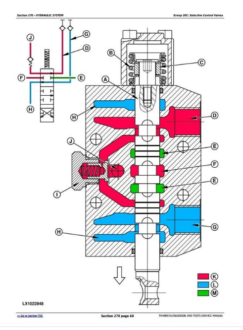
Selective Control Valves
Special Tools
Special Tools (Dealer-Fabricated)
Special Tools (Available as Spare Parts)
tm400919 - 6225 to 6525TractorsDiagnostics
Table of Contents
Foreword
Section 210: General Information
Group 05: Safety Information
General Information - Safety - Summary of References
Recognize Safety Information
”Important” Information
”Note” Information
Prevent Machine Runaway
Handle Fluids Safely—Avoid Fires
Prevent Battery Explosions
Prepare for Emergencies
Prevent Acid Burns
Avoid High-Pressure Fluids
Service Cooling System Safely
Remove Paint Before Welding or Heating
Avoid Heating Near Pressurized Fluid Lines
Work In Ventilated Area
Wear Protective Clothing
Practice Safe Maintenance
Park Machine Safely
Use Proper Lifting Equipment
Construct Dealer-Made Tools Safely
Support Machine Properly
Work in Clean Area
Illuminate Work Area Safely
Service Machines Safely
Use Proper Tools
Service Tires Safely
Service Front-Wheel Drive Tractor Safely
Safety Information - Air Brake System
Avoid Eye Contact With Radar
Keep ROPS Installed Properly
Replace Safety Signs
Replace Safety Signs
Dispose of Waste Properly
Live With Safety
Safety Measures on Electronic Control Units
Servicing Electronic Control Units
Welding Near Electronic Control Units
Keep Electronic Control Unit Connectors Clean
Safety Instructions for Replacing a Halogen Bulb
Safety Instructions for Replacing Xenon (HID) Bulbs and Ballast Units
Group 10: General References
General Information - General References, Summary of References
General Information - Transmission and Hydraulic System, Introductory Checks
General Information - Inch Bolt and Cap Screws, Torque Values
General Information - Metric Bolt and Cap Screws, Torque Values
General Information - Hydraulic System Inch Fittings, Torque Values
General Information - Hydraulic System Metric Fittings, Torque Values
General Information - Electrical System, Component Identification Table
General Information - Electrical System, How to Read a Diagnostic Schematic
General Information - Electrical System, Lead Numbers and Color Codes
General Information - Electrical System, Symbols in Schematic, Wiring and Harness Diagrams
General Information - Electrical System, Approach to Tabular Diagnostic Procedures
General Information - Electrical System, Troubleshooting Unsolved Problems
General Information - Electrical System, Worksheet for Circuit/Harness Test
General Information - Electrical System, Visual Check
General Information - Electrical System, Electrical Circuit Malfunctions
General Information - Electrical System, Seven-Step Test Procedure
General Information - Hydraulic System, Symbols in Circuit Diagrams
General Information - Check the Oil Sight-Glass (when the Tire Combination has been Changed)
General Information - Country Version
Section 211: Diagnostic Trouble Codes
Group ECU: ECU Control Unit
ECU 000029.03 - B96 - Hand Throttle Potentiometer, Voltage Too High
ECU 000029.04 - B96 - Hand Throttle Potentiometer, Voltage Too Low
ECU 000091.03 - B79 - Accelerator Pedal Potentiometer, Voltage Too High
ECU 000091.04 - B79 - Accelerator Pedal Potentiometer, Voltage Too Low
ECU 000097.03 - Water-in-Fuel Sensor Signal Voltage Too High
ECU 000097.04 - Water-in-Fuel Sensor Signal Voltage Too Low
ECU 000097.16 - Water In Fuel Detected
ECU 000105.00 - Intake Air Temperature Extremely High
ECU 000105.03 - Intake Air Temperature Sensor Input Voltage Too High
ECU 000105.04 - Intake Air Temperature Sensor Input Voltage Too Low
ECU 000105.15 - Intake Air Temperature Slightly Too High
ECU 000105.16 - Intake Air Temperature Slightly High
ECU 000108.02 - Barometric Air Pressure Invalid
ECU 000110.00 - Engine Coolant Temperature Extremely High
ECU 000110.03 - Engine Coolant Temperature Sensor Input Voltage Too High
ECU 000110.04 - Engine Coolant Temperature Sensor Input Voltage Too Low
ECU 000110.15 - Engine Coolant Temperature Slightly High
ECU 000110.16 - Engine Coolant Temperature Moderately High
ECU 000157.03 - Fuel Rail Pressure Sensor Input Voltage Too High
ECU 000157.04 - Fuel Rail Pressure Sensor Input Voltage Too Low
ECU 000157.10 - Fuel Rail Pressure Loss Detected
ECU 000157.17 - Fuel Rail Pressure Not Developed
ECU 000158.17 - ECU Power Down Error
ECU 000174.00 - Fuel Temperature Extremely High
ECU 000174.03 - Fuel Temperature Sensor Input Voltage Too High
ECU 000174.04 - Fuel Temperature Sensor Input Voltage Too Low
ECU 000174.16 - Fuel Temperature Moderately High
ECU 000189.00 - Engine Speed Derate
ECU 000190.00 - Engine Overspeed Extreme
ECU 000190.16 - Engine Overspeed Moderate
ECU 000611.03 - Electronic Injector Wiring Shorted To Power Source
ECU 000611.04 - Electronic Injector Wiring Shorted To Ground
ECU 000627.01 - High Resistance In All Injector Circuits
ECU 000629.12 - ECU Error (EEPROM)
ECU 000629.13 - ECU Error
ECU 000636.02 - Pump Position Sensor Input Noise
ECU 000636.05 - Pump Position Sensor Current Too Low
ECU 000636.06 - Pump Position Sensor Current Too High
ECU 000636.08 - Pump Position Sensor Input Missing
ECU 000636.10 - Pump Position Sensor Input Pattern Error
ECU 000637.02 - Crank Sensor Input Noise
ECU 000637.05 - Crank Sensor Current Too Low
ECU 000637.06 - Crank Sensor Current Too High
ECU 000637.07 - Crank Position/Pump Position Timing Moderately Out of Sync
ECU 000637.08 - Crank Sensor Signal Input Missing
ECU 000637.10 - Crank Sensor Input Pattern Error
ECU 000651.02 - Cylinder No.1 Electronic Injector Part Number Invalid
ECU 000651.05 - Cylinder No.1 Electronic Injector Circuit Open
ECU 000651.06 - Cylinder No.1 Electronic Injector Circuit Shorted
ECU 000651.13 - Calibration Fault, Cylinder No.1 Injector
ECU 000652.02 - Cylinder No.2 Electronic Injector Part Number Invalid
ECU 000652.05 - Cylinder No.2 Electronic Injector Circuit Open
ECU 000652.06 - Cylinder No.2 Electronic Injector Circuit Shorted
ECU 000652.13 - Calibration Fault, Cylinder No.2 Injector
ECU 000653.02 - Cylinder No.3 Electronic Injector Part Number Invalid
ECU 000653.05 - Cylinder No.3 Electronic Injector Circuit Open
ECU 000653.06 - Cylinder No.3 Electronic Injector Circuit Shorted
ECU 000653.13 - Calibration Fault, Cylinder No.3 Injector
ECU 000654.02 - Cylinder No.4 Electronic Injector Part Number Invalid
ECU 000654.05 - Cylinder No.4 Electronic Injector Circuit Open
ECU 000654.06 - Cylinder No.4 Electronic Injector Circuit Shorted
ECU 000654.13 - Calibration Fault, Cylinder No.4 Injector
ECU 000655.02 - Cylinder No.5 Electronic Injector Part Number Invalid
ECU 000655.05 - Cylinder No.5 Electronic Injector Circuit Open
ECU 000655.06 - Cylinder No.5 Electronic Injector Circuit Shorted
ECU 000655.13 - Calibration Fault, Cylinder No.5 Injector
ECU 000656.02 - Cylinder No.6 Electronic Injector Part Number Invalid
ECU 000656.05 - Cylinder No.6 Electronic Injector Circuit Open
ECU 000656.06 - Cylinder No.6 Electronic Injector Circuit Shorted
ECU 000656.13 - Calibration Fault, Cylinder No.6 Injector
ECU 000676.03 - Glow Plug Relay Voltage Too High
ECU 000676.05 - Glow Plug Relay Voltage Too Low
ECU 001347.03 - Suction Control Valve Current Too High
ECU 001347.05 - Suction Control Valve Current Mismatch
ECU 001347.07 - Fuel Rail Pressure Control Error
ECU 001569.31 - Fuel Derate
ECU 003509.03 - Sensor Supply Voltage 1 Too High
ECU 003509.04 - Sensor Supply Voltage 1 Too Low
ECU 003510.03 - Sensor Supply Voltage 2 Too High
ECU 003510.04 - Sensor Supply Voltage 2 Too Low
ECU 003511.03 - Sensor Supply Voltage 3 Too High
ECU 003511.04 - Sensor Supply Voltage 3 Too Low
Section 212: Observable Symptoms
Group 40: Electrical System
Control Unit not Displayed
Problems with the CAN-BUS Connection to Service ADVISOR
Problems While Reprogramming Control Units
Charging Circuit Problem
Problem with the Starting Motor
Problem with the Battery
Problem with Fuel Preheater Element
Problem with the Fuel Pump
Problem with Heating Element of Electrical Starting Aid (2-Valve Engine with HPCR)
Problem with the Instrument Unit
Problem with the Horn
Problem with the Parking Lights
Problem with the Low-Beam Headlights
Problem with the High-Beam Headlights
Problem with the Front Corner Worklights
Problem with Worklights on Rear Fenders
Problem with the 3-Terminal Power Outlet Socket
Problem with the 2-Pin Plug of Front Loader
Problem with the Hazard Warning Lights
Problem with the Turn Signals
Problem with Brake Lights
Problem with the Differential Lock
Problem with the Front-Wheel Drive
Problem with the 7-Terminal Power Outlet Socket
Group 50: SyncroPlus Transmission
Problem with SyncroPlus Transmission
Group 51: PowrReverser Transmission
Problem with PowrReverser Transmission
Group 56: Drive Systems
Problem with the rear PTO
Problem with the Front-Wheel Drive
Problem with the Differential Lock
Group 60: Steering and Brakes
Problem with the Brakes
Problem with the Steering
Problem with the Handbrake
Group 70: Hydraulic System
Hitch lowers too fast
Hitch: Incorrect reaction of position or draft control
Hitch: Lift arms rise too slowly or erratically
Section 213: System Diagnostics
Group 45: Electronics
Check for Vehicle CAN BUS
Section 220: Engine
Group 05: General Information
Information on Engine
Group 10: Operational Checks
Engine - Safety Measures