
John Deere 1720 1725 SeedStar 16 Row Planter Diagnostic & Tests Service Manual TM118219 PDF - MJODTM118219.zip
Full Diagnosis & Testing Service Guide featuring electrical schematics for the John Deere SeedStar 16 Row Planters, Models 1720 and 1725 Planter (Frame and Hydraulics), packed with the technical data needed to maintain, troubleshoot, and repair these machines the way expert technicians do.
The John Deere 1720, 1725 SeedStar 16 Row Planter (SN.745101-) workshop Diagnosis & Tests technical manual contains:
* Numbered table of contents easy to use so that you can find the information you need fast.
* Detailed sub-steps expand on repair procedure information
* Numbered instructions guide you through every repair procedure step by step.
* Troubleshooting and electrical service procedures are combined with detailed wiring diagrams for ease of use.
* Notes, cautions and warnings throughout each chapter pinpoint critical information.
* Bold figure number help you quickly match illustrations with instructions.
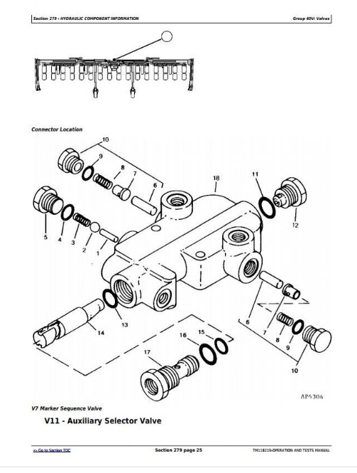
* Detailed illustrations, drawings and photos guide you through every procedure.
* Enlarged inset helps you identify and examine parts in detail.
tm118219 - 1720, 172516 Row Planter (SN745101 - XXXXXX) SeedStarTM, Frame, and Hydraulics Diagnosis and Tests Technical Manual.pdf
PRODUCT DETAILS:
Total Pages: 1,143 pages
File Format: PDF (bookmarked, ToC, Searchable, Printable, high quality)
Language: English
MAIN SECTIONS
Foreword
General Information
Acronym Table
How to Use This Manual
Safety
Lubricants
Accessing Diagnostic Addresses and Codes
Recommended Tools for Diagnostics
Diagnostic Information for Electrical Components
Diagnostic Information for Hydraulic Components
Maintaining Hydraulic Systems and Components
Basic Diagnostics
Standard Torque Chart Procedures
Diagnostic Trouble Codes
Accessing Diagnostic Trouble Codes
PM1 - Planter Main 1 Codes
PM2 - Planter Main 2 Codes
Observable Symptoms and System Diagnostics
Observable Symptoms
Electrical System
Theory of Operation
Schematics
Diagnostics
Electrical Control Units
Accessing Diagnostic Addresses
Diagnostic Addresses by Control Unit
Diagnostics
Electrical Component Information
Assembly Connectors
Sensor Connectors
Light Connectors
Fuse Connectors
Battery Connectors
Relay Connectors
Motor Connectors
Resistor Connectors
Switch Connectors
Harness Interconnects
Solenoid Connectors
Hydraulic System
Theory of Operation
Schematics
Diagnostics
Hydraulic Component Information
Cylinders
Filters
Assemblies
Oil Coolers
Motors
Orifices
Reservoirs
Valves
Couplers
Solenoid Valves
Pneumatic System
Theory of Operation
Schematics
Diagnostics
Pneumatic Component Information
Accumulators
Sensors
Check Valves
Filters
Assemblies
Motors
Pumps
Reservoirs
Switches
Valves
Couplers
Solenoid Valves
tm118219 - 1720, 172516 Row Planter (SN745101 - XXXXXX) SeedStar™, Frame, and Hydraulics Diagnosis and Tests
Table of Contents
Foreword
Section 210: General Information
Group 10: Acronym Table
Acronym Table
Group 05A: How to Use This Manual
Information is Available in Sections, Groups and Subgroups
Group 05B: Safety
Work In Ventilated Area
Recognize Safety Information
Avoid Backover Accidents
Prevent Machine Runaway
Avoid Contact with Agricultural Chemicals
Clean Vehicle of Hazardous Pesticides
Use a Safety Chain
Work in Clean Area
Decommissioning — Proper Recycling and Disposal of Fluids and Components
Prepare for Emergencies
In Case of Fire
Use Safety Lights and Devices
Avoid High-Pressure Fluids
Use Proper Lifting Equipment
Illuminate Work Area Safely
Live With Safety
Service Machines Safely
Support Machine Properly
Freeing a Mired Machine
Protect Against Noise
Remove Paint Before Welding or Heating
Park Machine Safely
Prevent Acid Burns
Follow Safety Instructions
Follow Safety Instructions
Use Proper Tools
Keep Riders Off Machine
Service Tires Safely
Stay Clear of Rotating Drivelines
Construct Dealer-Made Tools Safely
Practice Safe Maintenance
Understand Signal Words
Replace Safety Signs
Prevent Battery Explosions
Protect Against High Pressure Spray
Service Tires Safely
Avoid Heating Near Pressurized Fluid Lines
Tow Loads Safely
Transport Towed Equipment at Safe Speeds
Observe Maximum Transport Speed
Wear Protective Clothing
Precautions for Welding
Handle Agricultural Chemicals Safely
Service and Operate Chemical Sprayers Safely
Relieve Hydraulic Pressure Safely
Use Steps and Handholds Correctly
Group 05C: Lubricants
Grease
Gear Oil
Alternative and Synthetic Lubricants
Lubricant Storage
Group 05D: Accessing Diagnostic Addresses and Codes
Accessing Diagnostic Addresses
Accessing Diagnostic Trouble Codes
Group 05E: Recommended Tools for Diagnostics
Recommended Tools
Group 05F: Diagnostic Information for Electrical Components
Electrical Designators
Visually Inspect Electrical System
Group 05G: Diagnostic Information for Hydraulic Components
Hydraulic Designators
Troubleshooting Tips
Visually Inspect Hydraulic System
Group 05H: Maintaining Hydraulic Systems and Components
Hydraulic Components
Oil Storage and Filling
Oil Filtration
Group 05I: Basic Diagnostics
Seven Basic Steps
Troubleshooting Unresolved Problems
Group 05J: Standard Torque Chart Procedures
Unified Inch Bolt and Screw Torque Values
Metric Bolt and Screw Torque Values
Section 211: Diagnostic Trouble Codes
Group 10A: Accessing Diagnostic Trouble Codes
Accessing Diagnostic Trouble Codes
Group 10C: PM1 - Planter Main 1 Codes
PM1 000084.09 - Wheel Speed Not Detected On CAN Bus
PM1 000609.12 - Planter Module 2 Not Responding
PM1 000629.14 - Planter Disabled, Cycle Power
PM1 001859.09 - Radar Speed Not Detected On CAN Bus
PM1 001859.10 - Ground Speed and Tractor Speed Conflict
PM1 001859.14 - Minimum Speed Not Reached At End Of Quickstart
PM1 003509.03 - 5 Volt Sensor Supply Voltage High
PM1 003509.04 - 5 Volt Sensor Supply Voltage Low
PM1 003510.03 - 8 Volt Sensor Supply Voltage High
PM1 003510.04 - 8 Volt Sensor Supply Voltage Low
PM1 005109.12 - Planter Module 3 Not Responding
PM1 005117.01 - EPM 1 Input Voltage Low
PM1 005117.02 - EPM 1 Not Responding To Setup
PM1 005117.12 - EPM 1 Offline
PM1 005117.18 - EPM 1 Low Voltage On Inputs
PM1 005118.01 - EPM 2 Input Voltage Low
PM1 005118.02 - EPM 2 Not Responding To Setup
PM1 005118.12 - EPM 2 Offline
PM1 005118.18 - EPM 2 Low Voltage On Inputs
PM1 520328.02 - Seed Detected On Row 1 While Deactivated
PM1 520328.12 - Row 1 Clutch Failed
PM1 521037.03 - Vacuum 1 Sensor Voltage High
PM1 521037.04 - Vacuum 1 Sensor Voltage Low
PM1 521037.17 - Vacuum 1 Pressure Low
PM1 521124.03 - Vacuum 2 Sensor Voltage High
PM1 521124.04 - Vacuum 2 Sensor Voltage Low
PM1 521124.17 - Vacuum 2 Pressure Low
PM1 521633.07 - VRD 1 Frequency Low
PM1 521633.10 - VRD 1 Frequency Abnormal
PM1 521726.07 - VRD 2 Frequency Low
PM1 521726.10 - VRD 2 Frequency Abnormal
PM1 521883.07 - VRD 3 Frequency Low
PM1 521883.10 - VRD 3 Frequency Abnormal
PM1 522260.02 - Motion Sensor Speed and Tractor Speed Conflict
PM1 522260.10 - Motion Sensor Responding When No Active Tractor Speed
PM1 522336.02 - Seed Detected On Row 16 While Deactivated
PM1 522336.12 - Row 16 Clutch Failed
PM1 522337.02 - Seed Detected On Row 15 While Deactivated
PM1 522337.12 - Row 15 Clutch Failed
PM1 522338.02 - Seed Detected On Row 14 While Deactivated
PM1 522338.12 - Row 14 Clutch Failed
PM1 522339.02 - Seed Detected On Row 13 While Deactivated
PM1 522339.12 - Row 13 Clutch Failed
PM1 522342.02 - Seed Detected On Row 12 While Deactivated
PM1 522342.12 - Row 12 Clutch Failed
PM1 522346.02 - Seed Detected On Row 11 While Deactivated
PM1 522346.12 - Row 11 Clutch Failed
PM1 522347.02 - Seed Detected On Row 10 While Deactivated
PM1 522347.12 - Row 10 Clutch Failed
PM1 522348.02 - Seed Detected On Row 9 While Deactivated
PM1 522348.12 - Row 9 Clutch Failed
PM1 522349.02 - Seed Detected On Row 8 While Deactivated
PM1 522349.12 - Row 8 Clutch Failed
PM1 522351.02 - Seed Detected On Row 7 While Deactivated
PM1 522351.12 - Row 7 Clutch Failed
PM1 522352.02 - Seed Detected On Row 6 While Deactivated
PM1 522352.12 - Row 6 Clutch Failed
PM1 522353.02 - Seed Detected On Row 5 While Deactivated
PM1 522353.12 - Row 5 Clutch Failed
PM1 522354.02 - Seed Detected On Row 4 While Deactivated
PM1 522354.12 - Row 4 Clutch Failed
PM1 522355.02 - Seed Detected On Row 3 While Deactivated
PM1 522355.12 - Row 3 Clutch Failed
PM1 522356.02 - Seed Detected On Row 2 While Deactivated
PM1 522356.12 - Row 2 Clutch Failed
PM1 522941.11 - Selected Ground Speed Source is Wheel
PM1 522941.14 - Selected Ground Speed Source is Manual
PM1 522942.09 - Planting Parameters Satisfied Before Controller Initialized
PM1 523111.14 - Reset System Parameters
PM1 523170.31 - Row 16 Seed Sensor Not Responding
PM1 523171.31 - Row 15 Seed Sensor Not Responding
PM1 523172.31 - Row 14 Seed Sensor Not Responding
PM1 523173.31 - Row 13 Seed Sensor Not Responding
PM1 523174.31 - Row 12 Seed Sensor Not Responding
PM1 523175.31 - Row 11 Seed Sensor Not Responding
PM1 523176.31 - Row 10 Seed Sensor Not Responding
PM1 523177.31 - Row 9 Seed Sensor Not Responding
PM1 523178.31 - Row 8 Seed Sensor Not Responding
PM1 523179.31 - Row 7 Seed Sensor Not Responding
PM1 523180.31 - Row 6 Seed Sensor Not Responding
PM1 523181.31 - Row 5 Seed Sensor Not Responding
PM1 523182.31 - Row 4 Seed Sensor Not Responding
PM1 523183.31 - Row 3 Seed Sensor Not Responding
PM1 523184.31 - Row 2 Seed Sensor Not Responding
PM1 523185.31 - Row 1 Seed Sensor Not Responding
PM1 523194.31 - Rows Not Planting
PM1 523319.03 - ECU Power Voltage High
PM1 523319.04 - ECU Power Voltage Low
PM1 523328.11 - Height Sensor Not Calibrated
PM1 523328.14 - Height Sensor Below Normal Operating Range
PM1 523436.31 - Watchdog Reset For Seed Monitor
PM1 523651.11 - Internal Stack Overflow
PM1 523652.03 - High Current Power Voltage High
PM1 523652.04 - High Current Power Voltage Low
PM1 523705.31 - Watchdog Reset For Seed Monitor And VRD
PM1 523773.03 - CAN High Voltage High
PM1 523773.04 - CAN High Voltage Low
PM1 523774.03 - CAN Low Voltage High
PM1 523774.04 - CAN Low Voltage Low
PM1 524054.14 - Specified Area Has Been Planted
PM1 524055.11 - Stored NOVRAM Value Abnormal
Group 10D: PM2 - Planter Main 2 Codes
PM2 000609.02 - Seed Monitor Not Responding
PM2 000609.12 - Seed Monitor Offline
PM2 000629.12 - Watchdog Timed Out
PM2 000639.12 - Implement CAN Bus Lost Message
PM2 000639.14 - Implement CAN Bus Excessive Errors
PM2 000705.13 - Node 1 Sensor Calibration Error
PM2 000705.19 - Node 1 Downforce Sensor Error
PM2 000706.13 - Node 2 Sensor Calibration Error
PM2 000706.19 - Node 2 Downforce Sensor Error
PM2 000707.13 - Node 3 Sensor Calibration Error
PM2 000707.19 - Node 3 Downforce Sensor Error
PM2 001231.12 - Left CAN Bus Lost Message
PM2 001231.14 - Left CAN Bus Excessive Errors
PM2 001235.12 - Right CAN Bus Lost Message
PM2 001235.14 - Right CAN Bus Excessive Errors
PM2 001351.14 - Compressor Motor Time Limit Exceeded
PM2 003509.03 - 5 Volt Sensor Supply Voltage High
PM2 003509.04 - 5 Volt Sensor Supply Voltage Low
PM2 005111.02 - Node 1 Message Missing
PM2 005111.12 - Node 1 Missing
PM2 005111.19 - Node 1 Accelerometer Fault
PM2 005112.02 - Node 2 Message Missing
PM2 005112.12 - Node 2 Missing
PM2 005112.19 - Node 2 Accelerometer Fault
PM2 005113.02 - Node 3 Message Missing