
Hyundai HW140 Wheeled Excavator Service Repair Manual PDF Download with Wiring Diagrams - MHYCOHW140.zip
A full-service repair guide featuring complete electrical wiring schematics for the Hyundai HW140 Wheeled Excavator, packed with the technical detail needed to service, troubleshoot, and rebuild the machine just like a professional technician would.
The Hyundai HW140 Wheeled Excavator workshop service and repair manual covers:
* Numbered table of contents easy to use so that you can find the information you need fast.
* Detailed sub-steps expand on repair procedure information
* Numbered instructions guide you through every repair procedure step by step.
* Troubleshooting and electrical service procedures are combined with detailed wiring diagrams for ease of use.
* Notes, cautions and warnings throughout each chapter pinpoint critical information.
* Bold figure number help you quickly match illustrations with instructions.
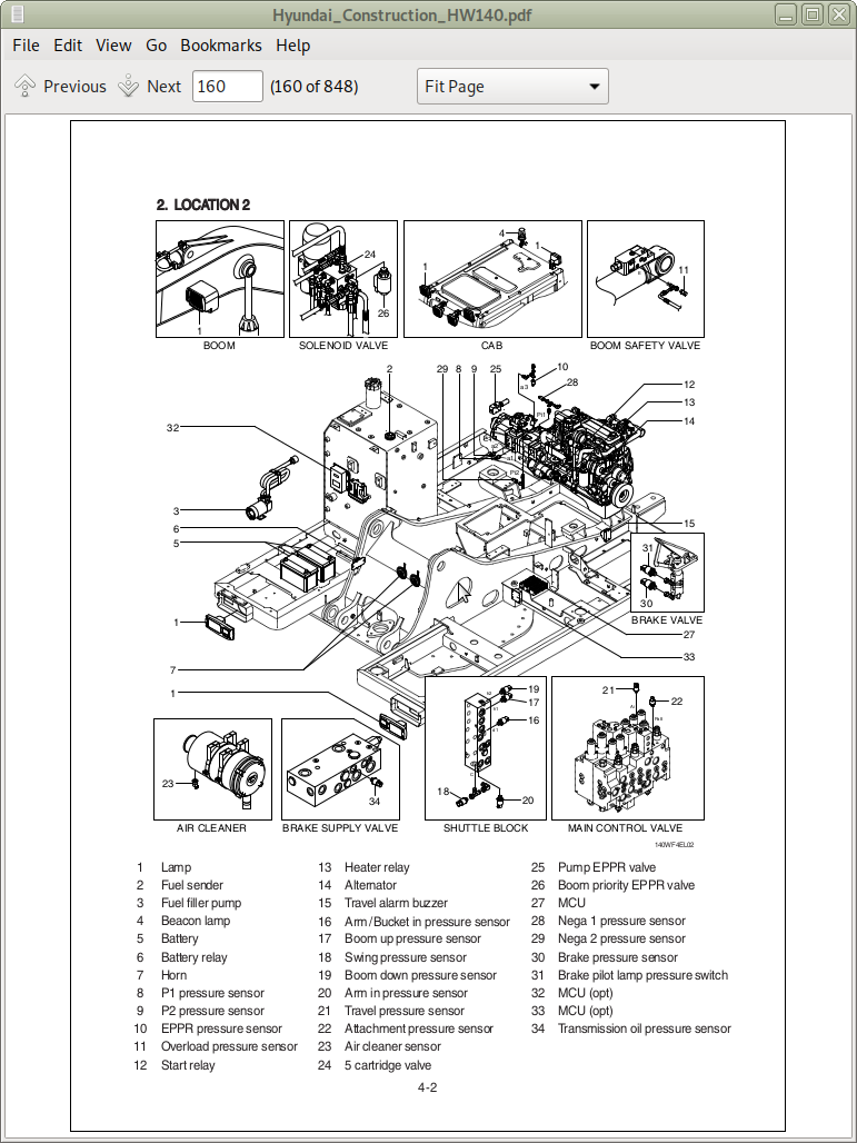
* Detailed illustrations, drawings and photos guide you through every procedure.
* Enlarged inset helps you identify and examine parts in detail.
PRODUCT DETAILS:
Total Pages: 844 pages
File Format: PDF (Internal Links, Bookmarked, Table of Contents, Searchable, Printable, high quality)
Language: English
TABLE OF CONTENTS
SECTION 1 GENERAL
Group 1 Safety Hints - - 1-1
Group 2 Specifications - - 1-9
SECTION 2 STRUCTURE AND FUNCTION
Group 1 Pump Device - - 2-1
Group 2 Main Control Valve - - 2-20
Group 3 Swing Device - - 2-47
Group 4 Travel Motor - - 2-58
Group 5 RCV Lever - - 2-64
Group 6 Accelerator Pedal - - 2-71
Group 7 Brake Pedal (Valve) - - 2-72
Group 8 Transmission - - 2-74
Group 9 Travel Control Valve - - 2-81
Group 10 Steering Valve - - 2-83
Group 11 Front Axle and Rear Axle - - 2-85
SECTION 3 HYDRAULIC SYSTEM
Group 1 Hydraulic Circuit - - 3-1
Group 2 Main Circuit - - 3-3
Group 3 Pilot Circuit - - 3-6
Group 4 Single Operation - - 3-17
Group 5 Combined Operation - - 3-32
SECTION 4 ELECTRICAL SYSTEM
Group 1 Component Location - - 4-1
Group 2 Electrical Circuit - - 4-3
Group 3 Electrical Component Specification - - 4-25
Group 4 Connectors - - 4-37
SECTION 5 MECHATRONICS SYSTEM
Group 1 Outline - - 5-1
Group 2 Mode selection System - - 5-3
Group 3 Automatic Deceleration System - - 5-6
Group 4 Power Boost System - - 5-7
Group 5 Travel Speed Control System - - 5-8
Group 6 Automatic Warming Up Function - - 5-9
Group 7 Engine Overheat Prevention Function - - 5-10
Group 8 Variable Power Control System - - 5-11
Group 9 Attachment Flow Control System - - 5-12
Group 10 Boom Floating Control System - - 5-13
Group 11 Intelligent Power Control System - - 5-14
Group 12 Anti-Restart System - - 5-16
Group 13 Self-Diagnostic System - - 5-17
Group 14 Engine Control System - - 5-54
Group 15 EPPR Valve - - 5-55
Group 16 Monitoring System - - 5-60
Group 17 Fuel Warmer System - - 5-100
SECTION 6 TROUBLESHOOTING
Group 1 Before Troubleshooting - - 6-1
Group 2 Hydraulic and Mechanical System - - 6-4
Group 3 Electrical System - - 6-25
Group 4 Mechatronics System - - 6-41
SECTION 7 MAINTENANCE STANDARD
Group 1 Operational Performance Test - - 7-1
Group 2 Major Components - - 7-19
Group 3 Track and Work Equipment - - 7-28
SECTION 8 DISASSEMBLY AND ASSEMBLY
Group 1 Precaution - - 8-1
Group 2 Tightening Torque - - 8-4
Group 3 Pump Device - - 8-7
Group 4 Main Control Valve - - 8-30
Group 5 Swing Device - - 8-44
Group 6 Travel Motor - - 8-77
Group 7 Transmission - - 8-101
Group 8 Steering Valve - - 8-155
Group 9 Front Axle - - 8-180
Group 10 Rear Axle - - 8-251
Group 11 RCV Lever - - 8-293
Group 12 Turning Joint - - 8-307
Group 13 Boom, Arm, Bucket, Dozer and Outrigger Cylinders - - 8-313
Group 14 Work Equipment - - 8-335
SECTION 9 COMPONENT MOUNTING TORQUE
Group 1 Introduction Guide - - 9-1
Group 2 Engine System - - 9-2
Group 3 Electric System - - 9-4
Group 4 Hydraulic System - - 9-6
Group 5 Power train System - - 9-9
Group 6 Structure - - 9-11
Group 7 Work Equipment - - 9-15
Group 3 Automatic Deceleration System - - 5-6
Group 4 Power Boost System - - 5-7
Group 5 Travel Speed Control System - - 5-8
Group 6 Automatic Warming Up Function - - 5-9
Group 7 Engine Overheat Prevention Function - - 5-10
Group 8 Variable Power Control System - - 5-11
Group 9 Attachment Flow Control System - - 5-12
Group 10 Boom Floating Control System - - 5-13
Group 11 Intelligent Power Control System - - 5-14
Group 12 Anti-Restart System - - 5-16
Group 13 Self-Diagnostic System - - 5-17
Group 14 Engine Control System - - 5-54
Group 15 EPPR Valve - - 5-55
Group 16 Monitoring System - - 5-60
Group 17 Fuel Warmer System - - 5-100
SECTION 6 TROUBLESHOOTING
Group 1 Before Troubleshooting - - 6-1
Group 2 Hydraulic and Mechanical System - - 6-4
Group 3 Electrical System - - 6-25
Group 4 Mechatronics System - - 6-41
SECTION 7 MAINTENANCE STANDARD
Group 1 Operational Performance Test - - 7-1
Group 2 Major Components - - 7-19
Group 3 Track and Work Equipment - - 7-28
SECTION 8 DISASSEMBLY AND ASSEMBLY
Group 1 Precaution - - 8-1
Group 2 Tightening Torque - - 8-4
Group 3 Pump Device - - 8-7
Group 4 Main Control Valve - - 8-30
Group 5 Swing Device - - 8-44
Group 6 Travel Motor - - 8-77
Group 7 Transmission - - 8-101
Group 8 Steering Valve - - 8-155
Group 9 Front Axle - - 8-180
Group 10 Rear Axle - - 8-251
Group 11 RCV Lever - - 8-293
Group 12 Turning Joint - - 8-307
Group 13 Boom, Arm, Bucket, Dozer and Outrigger Cylinders - - 8-313
Group 14 Work Equipment - - 8-335
SECTION 9 COMPONENT MOUNTING TORQUE
Group 1 Introduction Guide - - 9-1
Group 2 Engine System - - 9-2
Group 3 Electric System - - 9-4
Group 4 Hydraulic System - - 9-6
Group 5 Power train System - - 9-9
Group 6 Structure - - 9-11
Group 7 Work Equipment - - 9-15
…
Hyundai Wheeled Excavator HW140 Repair Service Manual