
Komatsu PC600-8E0 PC600LC-8E0 PC650-8E0 PC650LC-8E0 PC700LC-8E0 Excavator Workshop Repair Service Manual PDF - MKMTSPC600E0PC700LCE0.zip
A full service and repair manual featuring Electrical Wiring Diagrams for the Komatsu Hydraulic Excavator PC600-8E0, PC600LC-8E0, PC650-8E0, PC650LC-8E0, and PC700LC-8E0, containing every technical detail needed to service, troubleshoot, fix, and rebuild these machines the way expert technicians do.
This workshop service repair manual for the Komatsu Hydraulic Excavator PC600-8E0, PC600LC-8E0, PC650-8E0, PC650LC-8E0, and PC700LC-8E0 contains:
* Numbered table of contents easy to use so that you can find the information you need fast.
* Detailed sub-steps expand on repair procedure information
* Numbered instructions guide you through every repair procedure step by step.
* Troubleshooting and electrical service procedures are combined with detailed wiring diagrams for ease of use.
* Notes, cautions and warnings throughout each chapter pinpoint critical information.
* Bold figure number help you quickly match illustrations with instructions.
* Detailed illustrations, drawings and photos guide you through every procedure.
* Enlarged inset helps you identify and examine parts in detail.
PRODUCT DETAILS:
Total Pages: 1,993 pages
File Format: PDF (Internal Links, Bookmarked, Table of Contents, Searchable, Printable, high quality)
Language: English
TEN00405-03 - Hydraulic Excavator PC600-8E0, PC600LC-8E0, PC650-8E0, PC650LC-8E0, PC700LC-8E0 Operation & Maintenance Manual.pdf
SEN05377-03 - Hydraulic Excavator PC600-8E0, PC600LC-8E0, PC650-8E0, PC650LC-8E0, PC700LC-8E0 Shop Manual.pdf
GEN00101-02 - Hydraulic Excavator PC600-8E0, PC600LC-8E0, PC650-8E0, PC650LC-8E0, PC700LC-8E0 Field Assembly Instruction.pdf
MAIN SECTIONS
GEN00101-02 - Hydraulic Excavator PC600-8E0, PC600LC-8E0, PC650-8E0, PC650LC-8E0, PC700LC-8E0 Field Assembly Instruction....2
COVER....2
FOREWORD....3
CONTENTS....4
SPECIFICATIONS....7
PRECAUTIONS FOR FIELD ASSEMBLY....9
DISPOSAL OF REMOVED PARTS....10
ASSEMBLING PROCEDURES, APPLICABLE EQUIPMENT AND SCHEDULE....11
KIT LAYOUT DIAGRAM....12
TRANSPORTATION....13
LIST OF TOOLS FOR FIELD ASSEMBLING....18
TIGHTENING TORQUE....19
COATING MATERIALS....24
SELECTION OF WIRE ROPES USED FOR ASSEMBLY....26
A. ASSEMBLY OF CHASSIS....27
A- 1. Installation of Left and Right Track Frames....28
A- 2. Installation of Travel Pipe....33
A- 3. Installation of Operator Cabs Left Handrail....38
A- 4. Installation of Operator Cabs Door Stopper and Striker....39
A- 5. Installation of Rearview Mirror....41
A- 6. Installation of Handrail....46
A- 7-1 Installation of Step....49
A- 7-2 Installation of Step....50
A- 8. Installation of Left Side Step....51
A- 9. Sticking Sheet to Counterweight....52
A-10. Installation of Rear View Camera....53
A-11. Installation of Counterweight....58
A-12. Installation of Step Light....60
A-13. Bleeding of Air from Travel Motor....62
A-14-1 Installation of Travel Piping Cover....63
A-14-2 Installation of Travel Piping Cover....67
A-15. Installation of Travel Motor Guard....70
A-16. Testing Track Shoe Tension....71
A-17. Check Fuel, Coolant and Oil Levels....74
B. ASSEMBLING OF WORK EQUIPMENT....77
B- 1. Assembly of Arm Cylinder....78
B- 2. Connection of Arm Cylinder Hoses....79
B- 3. Installation of Boom Cylinder....80
B- 4. Installation of Boom Cylinder Hoses....81
B- 5. Installation of Boom Foot Dust Seal....82
B- 6. Assembly of Boom Assembly....83
B- 7. Installation of Hoses from Chassis Along Top of Boom....84
B- 8. Connection of Boom Cylinder Head....86
B- 9. Installation of Arm Assembly....87
B-10. Installation of Bucket Cylinder Hoses between Boom and Bucket Cylinder....89
B-11. Installation of Bucket....90
B-12. Connection of Work Equipment Grease Piping....93
B-13. Connection of Work Equipment Wiring....94
B-14. Greasing after Assembling Work Equipment....96
B-15. Bleeding Air from Work Equipment Circuit....97
B-16. Parts to be Touched up After Field Assembly....98
C. Assembling of Work Equipment of Loading Shovel....99
C- 1. Releasing residual pressure in hydraulic circuit....100
C- 2. Pulling out boom foot pin and boom cylinder foot pin....101
C- 3. Installation of boom cylinder foot....102
C- 4. Installation of boom and arm assembly....103
C- 5. Installation of boom cylinder hoses....104
C- 6. Installation of boom cylinder rod pin....105
C- 7. Installation of boom cylinder....106
C- 8. Installation of arm cylinder hoses....107
C- 9. Installation of bucket cylinder....108
C-10. Installation of bucket cylinder hoses....109
C-11. Installation of connecting hoses between chassis and boom top....110
C-12. Installation of bottom dump cylinder hoses....111
C-13. Installation of bucket assembly....112
C-14. Installation of working lamps....114
C-15. Installation of work equipment grease piping....116
C-16. Greasing after assembling of work equipment....117
C-17. Bleeding air from work equipment circuit....118
C-18. Checking oil level in hydraulic tank and adding oil....119
D. ASSEMBLING OF COUNTERWEIGHT REMOVER....121
D- 1. Sticking Sheet to Counterweight....122
D- 2. Adjustment of Shims for Counterweight....123
D- 3. Greasing....128
D- 4. Installation of Counterweight Remover....129
D- 5. Installation of Covers....130
D- 6. Installation of Clamps....131
D- 7. Installation of Hoses....134
D- 8. Bleeding Air from Counterweight Remover Circuit....135
D- 9. Installation of Counterweight....136
D-10. Installation of Accessories....138
D-11. Check of Operation....139
M. PROCEDURE FOR INSPECTION AND MAINTENANCE AFTER COMPLETION OF ASSEMBLY....141
M- 1. Inspection of Oil Level in Hydraulic Tank and Refill....142
M- 2. Replacement of Return Filter (Standard Filter to Flushing Filter)....144
M- 3. Flushing of Hydraulic Circuit....147
M- 4. Failure code....149
M- 5. Operating Method of ....154
Field Assembly Inspection Report (Backhoe)....161
Field Assembly Inspection Report (Loading Shovel)....187
SEN05377-03 - Hydraulic Excavator PC600-8E0, PC600LC-8E0, PC650-8E0, PC650LC-8E0, PC700LC-8E0 Shop Manual....213
COVER....213
00 Index and foreword....223
Table of Contents....224
Table of Contents....224
Foreword and general information....234
Safety notice....234
How to read the shop manual....239
Explanation of terms for maintenance standard....241
Handling of hydraulic components....243
Method of disconnecting and connecting push-pull type coupler....245
Handling of electric equipment....248
How to read electric wire code....258
Precautions when performing work....261
Standard tightening torque table....264
List of abbreviation....268
Conversion table....272
01 Specification....277
Specifications....280
Specifications drawing....280
Working range drawings....282
Specifications....284
Table of weight....294
Table of fuel, coolant and lubricants....302
10 Structure and function....305
Engine and cooling system....307
Engine related parts....307
PTO....308
Cooling system....309
Power train system....310
Power train....310
Swing circle....312
Swing machinery....314
Final drive....316
Undercarriage and frame....318
Track frame and idler cushion....318
Hydraulic system....320
Hydraulic component layout....320
Valve control....322
Hydraulic tank and filter....324
Hydraulic pump (piston pump)....326
Cooling fan pump....354
Cooling fan motor....362
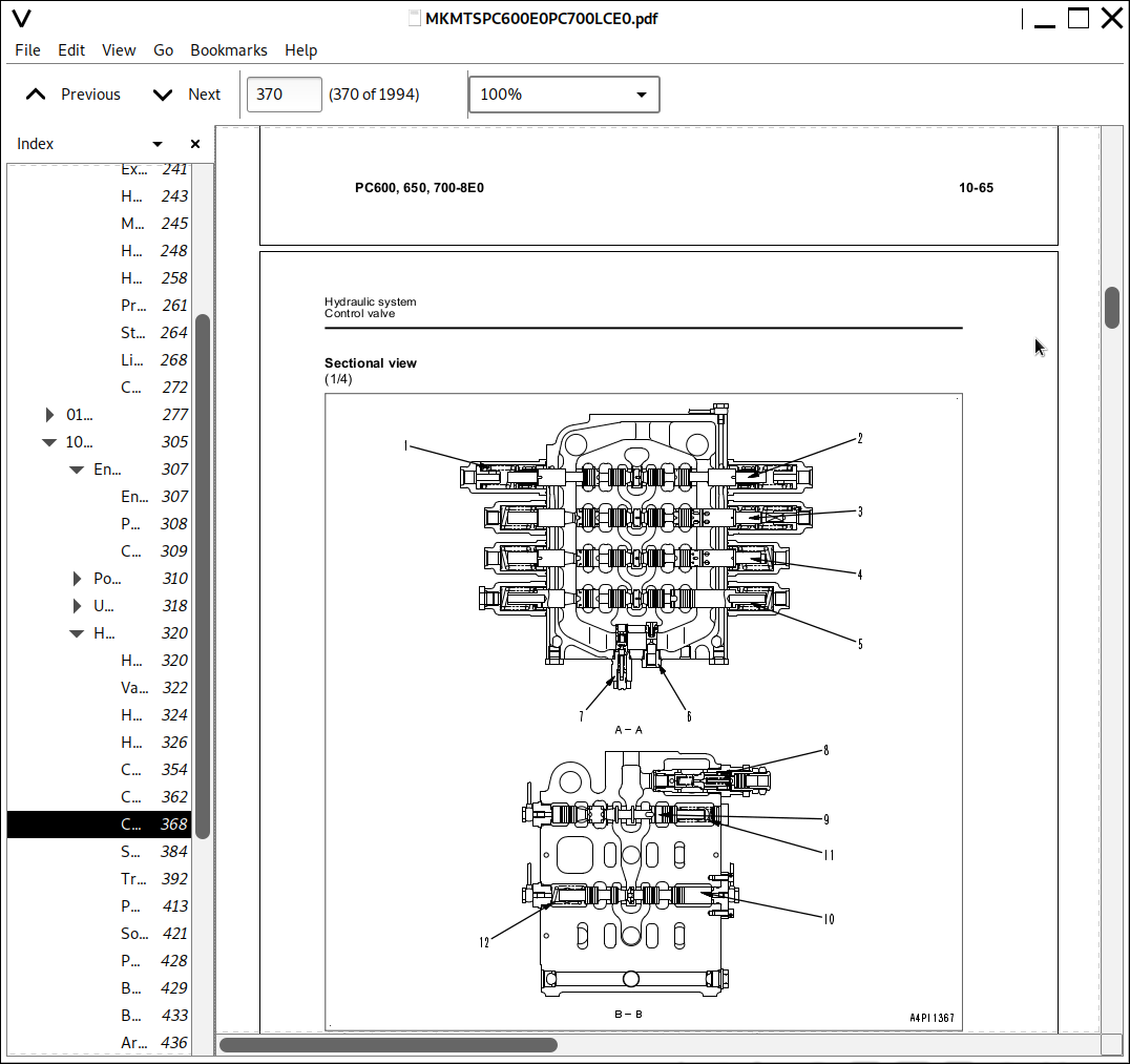
Control valve....368
Swing motor....384
Travel motor....392
PPC valve....413
Solenoid valve....421
PPC shuttle valve....428
Boom drift prevention valve....429
Boom LOWER regeneration valve....433
Arm regeneration valve....436
Quick return valve....439
Line oil filter....442
Center swivel joint....443
Accumulator....444
Electrical system....445
Engine control....445
Electrical control system....455
Monitor system....485
KOMTRAX system....511
Sensors....513
20 Standard value table....517
Standard value table....519
Standard value table for engine....519
Standard value table for machine....520
30 Testing and adjusting....543
Tool for testing, adjusting and troubleshooting....545
Tools for testing, adjusting, and troubleshooting....545
Engine and cooling system....549
Testing engine speed....549
Testing intake air pressure (boost pressure)....551
Testing exhaust gas temperature....552
Testing exhaust gas color....553
Testing and adjusting valve clearance....554
Testing compression pressure....555
Testing blowby pressure....557
Testing engine oil pressure....558
Testing EGR valve and bypass valve drive pressure....559
Handling fuel system parts....560
Releasing remaining pressure from fuel system....561
Testing fuel pressure....562
Cylinder cut-out test mode....563
No-injection cranking....564
Testing fuel return rate and leakage....565
Bleeding air from fuel circuit....568
Testing fuel circuit for leakage....570
Testing and adjusting alternator belt tension....571
Testing and adjusting air conditioner compressor belt tension....572
Undercarriage and frame....573
Testing swing circle bearing clearance....573
Checking and adjusting track tension....574
Hydraulic system....575
Testing and adjusting oil pressure in work equipment, swing and travel circuits....575
Testing and adjusting control circuit oil pressure....580
Testing and adjusting control oil pressure of piston pump....582
Testing servo piston movement....588
Testing PPC valve output pressure....590
Testing output pressure of solenoid valve and PPC shuttle valve....594
Adjusting play of work equipment and swing PPC vavles....600
Isolating the parts causing hydraulic drift in work equipment....601
Testing and adjusting travel deviation....603
Testing fan speed....605
Testing fan circuit oil pressure....606
Releasing remaining pressure from hydraulic circuit....607
Testing oil leakage....608
Bleeding air from each part....612
Electrical system....615
Special functions of machine monitor....615
Handling of voltage circuit of engine controller....659
Preparatory work for troubleshooting of electrical system....660
Inspection procedure of diode....665
Pm clinic....666
Pm Clinic service....666
UNDERCARRIAGE INSPECTION REPORT....678
40 Troubleshooting....681
General information on troubleshooting....688
Points to remember when troubleshooting....688
Sequence of events in troubleshooting....689
Checks before troubleshooting....690
Classification and procedures for troubleshooting....714
Failure codes table....717
Symptom and troubleshooting numbers....721
Information in troubleshooting table....724
Troubleshooting method for open circuit in wiring harness of pressure sensor system....726
Connector list and layout....728
Connection table for connector pin numbers....738
T- branch box and T- branch adapter table....774
Fuse locations....777
Troubleshooting by failure code....780
Failure code [989L00] Engine Controller Lock Caution 1....780
Failure code [989M00] Engine Controller Lock Caution 2....781
Failure code [989N00] Engine Controller Lock Caution 3....782
Failure code [AA10NX] Air Cleaner Clogging....783
Failure code [AB00KE] Charge Voltage Low....784
Failure code [B@BAZG] Eng Oil Press Low....786
Failure code [B@BAZK] Eng Oil Level Low....787
Failure code [B@BCNS] Eng Water Overheat....788
Failure code [B@BCZK] Eng Water Level Low....790
Failure code [B@HANS] Hyd Oil Overheat....792
Failure code [CA111] ECM Critical Internal Failure....794
Failure code [CA115] Eng Ne and Bkup Speed Sens Error....796
Failure code [CA122] Chg Air Press Sensor High Error....798
Failure code [CA123] Chg Air Press Sensor Low Error....800
Failure code [CA131] Throttle Sensor High Error....802
Failure code [CA132] Throttle Sensor Low Error....804
Failure code [CA135] Eng Oil Press Sensor High Error....806
Failure code [CA141] Eng Oil Press Sensor Low Error....808
Failure code [CA144] Coolant Temp Sens High Error....810
Failure code [CA145] Coolant Temp Sens Low Error....812
Failure code [CA153] Chg Air Temp Sensor High Error....814
Failure code [CA154] Chg Air Temp Sensor Low Error....816
Failure code [CA187] Sens Supply 2 Volt Low Error....818
Failure code [CA221] Ambient Press Sens High Error....820
Failure code [CA222] Ambient Press Sens Low Error....822
Failure code [CA227] Sens Supply 2 Volt High Error....824
Failure code [CA234] Eng Overspeed....825
Failure code [CA238] Ne Speed Sens Supply Volt Error....826
Failure code [CA263] Fuel Temp Sensor High Error....828
Failure code [CA265] Fuel Temp Sensor Low Error....830
Failure code [CA271] IMV/PCV1 Short Error....832
Failure code [CA272] IMV/PCV1 Open Error....833
Failure code [CA273] PCV2 Short Error....834
Failure code [CA274] PCV2 Open Error....835
Failure code [CA322] Inj #1(L#1) Open/Short Error....836
Failure code [CA323] Inj #5 (L#5) Open/Short Error....838
Failure code [CA324] Inj #3(L#3) Open/Short Error....840
Failure code [CA325] Inj #6 (L#6) Open/Short Error....842
Failure code [CA331] Inj #2(L#2) Open/Short Error....844
Failure code [CA332] Inj #4 (L#4) Open/Short Error....846
Failure code [CA342] Calibration Code Incompatibility....848
Failure code [CA351] Injectors Drive Circuit Error....849
Failure code [CA352] Sens Supply 1 Volt Low Error....850
Failure code [CA386] Sens Supply 1 Volt High Error....852
Failure code [CA441] Battery Voltage Low Error....852
Failure code [CA442] Battery Voltage High Error....853
Failure code [CA449] Rail Press Very High Error....853
Failure code [CA451] Rail Press Sensor High Error....854
Failure code [CA452] Rail Press Sensor Low Error....856
Failure code [CA553] Rail Press High Error....858
Failure code [CA554] Rail Press Sensor In Range Error....858
Failure code [CA559] Supply Pump Press Low Error 1....859
Failure code [CA689] Eng Ne Speed Sensor Error....862
Failure code [CA731] Eng Bkup Speed Sens Phase Error....864
Failure code [CA757] All Continuous Data Lost Error....865
Failure code [CA778] Eng Bkup Speed Sensor Error....866
Failure code [CA1228] EGR Valve Servo Error 1....868
Failure code [CA1625] EGR Valve Servo Error 2....869
Failure code [CA1626] BP Valve Sol Current High Error....870
Failure code [CA1627] BP Valve Sol Current Low Error....872
Failure code [CA1628] Bypass Valve Servo Error 1....874
Failure code [CA1629] Bypass Valve Servo Error 2....875