
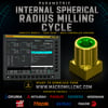
INTERNAL SPHERICAL RADIUS MILLING CYCLE

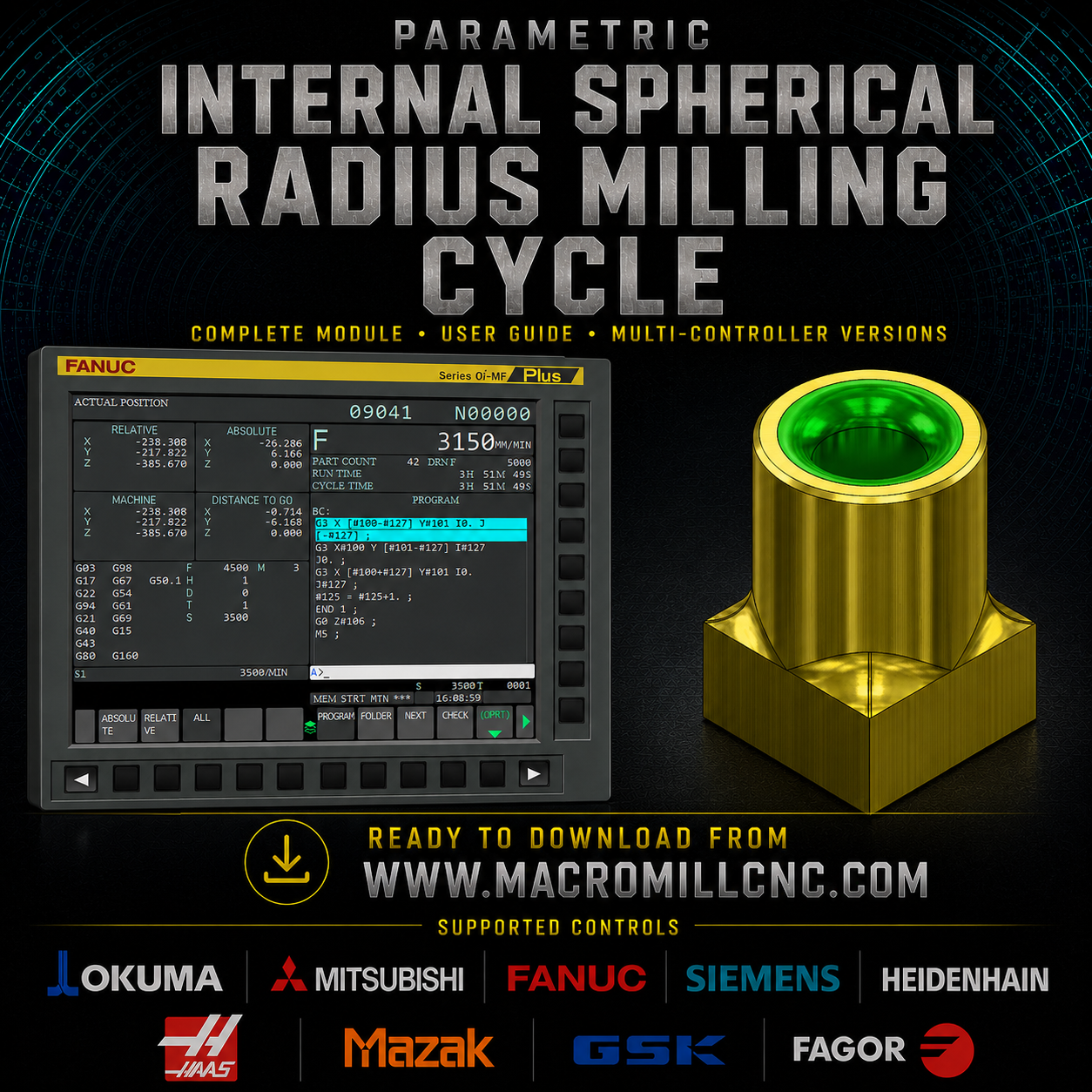
PARAMETRIC INTERNAL SPHERICAL RADIUS MILLING CYCLE
Complete Internal Spherical Radius Machining From One Reusable Parametric CNC Cycle
Machining an internal spherical radius normally requires a large CAM-generated 3D toolpath containing hundreds of circular passes and constantly changing X/Y/Z coordinates.
The Parametric Internal Spherical Radius Milling Cycle converts that complete machining strategy into one compact reusable parametric CNC cycle.
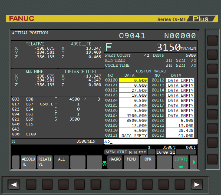
Enter the required internal spherical radius, start radial position, profile stepover, cutter diameter, cutter corner radius, machining feed and spindle speed — the cycle automatically calculates the complete internal spherical toolpath.
Machine the radius. Control the finish. Change the tool. Reuse the cycle.
Define the geometry. Run the cycle. Reuse it.
━━━━━━━━━━━━━━━━━━━━━━━━━━━━━━━━━━
⚙️ CYCLE CAPABILITIES
✅ 3-axis X/Y/Z CNC milling
✅ Parametric internal spherical radius machining
✅ Designed for internal concave radius features
✅ Ballnose cutter machining
✅ Corner-radius cutter support
✅ Editable finished spherical radius
✅ Editable start radial position
✅ Editable profile stepover
✅ Editable top Z position
✅ Editable X/Y feature center
✅ Editable tool diameter
✅ Editable tool corner radius
✅ Independent cutter diameter and corner-radius settings
✅ Automatic tool corner-radius compensation
✅ Automatic cutter-path radius calculation
✅ Automatic 90° spherical profile generation
✅ Automatic radial position calculation
✅ Automatic Z profile calculation
✅ SIN/COS-based profile generation
✅ Complete 360° circular machining passes
✅ Automatic profile division calculation
✅ Equalized profile progression
✅ Adjustable surface-finish stepover
✅ Adjustable cutting feed
✅ Adjustable spindle speed
✅ Adjustable clearance position
✅ Automatic final profile positioning
✅ Compact reusable macro structure
✅ Reusable for different spherical radii
✅ Reusable with different cutter sizes
✅ Simple operator-editable parameters
✅ Multi-controller versions included
━━━━━━━━━━━━━━━━━━━━━━━━━━━━━━━━━━
🔵 COMPLETE INTERNAL SPHERICAL MACHINING STRATEGY
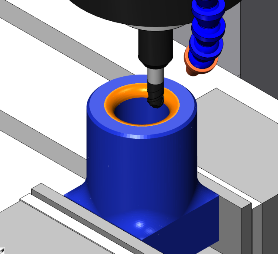
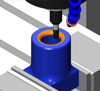
The cycle generates the complete concave internal spherical surface automatically.
Instead of storing hundreds of CAM-generated blocks, the cycle calculates each machining level mathematically.
At every calculated profile position, the cycle automatically performs:
✅ Radial position calculation
✅ Z-depth calculation
✅ Tool corner-radius compensation
✅ Complete 360° circular cutting pass
✅ Automatic progression to the next profile position
✅ Automatic final spherical-radius completion
The tool begins at the programmed outer radial position and progressively moves inward and downward along the spherical profile.
The complete internal radius is therefore created from a series of accurately calculated circular machining passes.
You define the feature dimensions — the macro controls the complete toolpath.
━━━━━━━━━━━━━━━━━━━━━━━━━━━━━━━━━━
🟢 PARAMETRIC INTERNAL SPHERICAL PROFILE
The internal radius is generated mathematically from the programmed finished spherical radius.
The macro automatically calculates the correct cutter-center path using the cutter corner radius.
Cutter Path Radius = Finished Spherical Radius − Tool Corner Radius
Example:
Finished spherical radius = 24 mm
Tool corner radius = 6 mm
Calculated cutter-path radius = 18 mm
The cycle then generates the complete 90° tool-center profile automatically.
This allows the operator to program the finished component radius directly instead of manually calculating every cutter-center coordinate.
━━━━━━━━━━━━━━━━━━━━━━━━━━━━━━━━━━
🛠️ EDITABLE TOOL DIAMETER & CORNER RADIUS
The cutter geometry is fully editable.
The cycle includes independent settings for:
✅ Tool diameter
✅ Tool corner radius
These values are deliberately kept separate.
For a full ballnose cutter:
12 mm ballnose = 12 mm tool diameter / 6 mm corner radius
10 mm ballnose = 10 mm tool diameter / 5 mm corner radius
16 mm ballnose = 16 mm tool diameter / 8 mm corner radius
For a corner-radius cutter:
12 mm cutter / R3
16 mm cutter / R4
20 mm cutter / R5
The operator simply enters the actual tool geometry.
The cycle automatically adjusts the cutter-center spherical profile accordingly.
━━━━━━━━━━━━━━━━━━━━━━━━━━━━━━━━━━
⚪ COMPLETE 360° CIRCULAR MACHINING
At every calculated spherical profile level, the cutter machines one complete 360° circular pass.
The toolpath remains centered on the programmed X/Y feature center.
Each pass automatically changes:
✅ Circular cutting radius
✅ Z position
The process continues until the complete internal spherical profile is reached.
The machining sequence can be visualized as:
Large circle at top → Slightly smaller circle / slightly deeper Z → Smaller circle / deeper Z → Progressive spherical profile → Final smallest circle at maximum spherical depth.
━━━━━━━━━━━━━━━━━━━━━━━━━━━━━━━━━━
📐 AUTOMATIC SPHERICAL GEOMETRY CALCULATION
The cycle uses trigonometric calculations to generate the spherical toolpath.
The profile is automatically divided across a 90° section.
At every division, the cycle calculates:
✅ Current profile angle
✅ Current radial cutter position
✅ Current Z position
✅ Current circular machining radius
The calculations use SIN and COS functions to maintain the correct spherical relationship.
The result is a true mathematically generated spherical profile rather than a simple linear X/Z interpolation.
━━━━━━━━━━━━━━━━━━━━━━━━━━━━━━━━━━
🔄 AUTOMATIC PROFILE DIVISION CALCULATION
The operator enters the required profile stepover.
Example:
Profile stepover = 0.25 mm
The cycle calculates the quarter-circle profile length automatically and determines the required number of profile divisions.
The complete 90° profile is divided equally so the final machining pass lands at the calculated spherical endpoint.
Smaller stepover:
✅ More machining passes
✅ Smoother surface
✅ Longer machining time
Larger stepover:
✅ Fewer machining passes
✅ Faster machining
✅ Coarser surface
The operator can therefore control machining time and surface finish from one parameter.
━━━━━━━━━━━━━━━━━━━━━━━━━━━━━━━━━━
📏 START RADIAL POSITION CONTROL
The start radial position controls where the cutter begins the spherical machining sequence.
Example:
Start radial position = 32 mm
Finished spherical radius = 24 mm
Tool corner radius = 6 mm
Cutter-path radius = 18 mm
Final radial position = 32 − 18 = 14 mm
The cycle therefore progresses automatically from:
R32 / Z0 → R14 / Z-18
━━━━━━━━━━━━━━━━━━━━━━━━━━━━━━━━━━
📉 AUTOMATIC Z PROFILE CALCULATION
The Z position is not reduced using a fixed depth step.
Every Z position is calculated directly from the spherical geometry.
Near the top of the radius, radial movement is larger while Z movement is very small.
Near the bottom of the radius, radial movement becomes smaller while Z movement becomes larger.
Typical calculated progression:
R32.000 / Z0.000
R31.750 / Z-0.002
R31.500 / Z-0.007
R31.250 / Z-0.016
R31.000 / Z-0.028
...
R14.043 / Z-16.750
R14.028 / Z-17.000
R14.016 / Z-17.250
R14.007 / Z-17.500
R14.002 / Z-17.750
R14.000 / Z-18.000
The macro calculates these positions automatically.
There is no need to manually generate or store hundreds of individual coordinates.
━━━━━━━━━━━━━━━━━━━━━━━━━━━━━━━━━━
🌀 BALLNOSE SURFACE MACHINING
The cycle is particularly suitable for ballnose cutters.
For a full ballnose:
Tool Corner Radius = Tool Diameter ÷ 2
Example:
Tool diameter = 12 mm
Tool corner radius = 6 mm
Finished spherical radius = 24 mm
Calculated cutter-center radius = 18 mm
The cycle automatically generates the compensated spherical toolpath.
━━━━━━━━━━━━━━━━━━━━━━━━━━━━━━━━━━
🔧 CORNER-RADIUS CUTTER SUPPORT
The tool diameter and corner radius are independent parameters, meaning the cycle is not restricted to full ballnose cutters.
Suitable examples include:
✅ 12 mm cutter R3
✅ 16 mm cutter R4
✅ 20 mm cutter R5
✅ Other suitable corner-radius cutters
Simply enter the actual cutter diameter and cutter corner radius.
The cycle automatically recalculates the cutter-center profile.
━━━━━━━━━━━━━━━━━━━━━━━━━━━━━━━━━━
🎯 X/Y FEATURE CENTER CONTROL
The spherical feature does not need to be positioned at X0 Y0.
The cycle includes editable:
✅ Center X
✅ Center Y
This allows the same cycle to machine spherical features at different component positions.
All circular passes remain automatically centered around the programmed X/Y coordinates.
━━━━━━━━━━━━━━━━━━━━━━━━━━━━━━━━━━
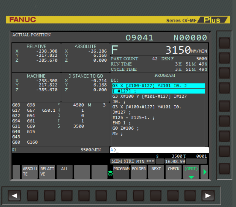
🚀 FANUC PARAMETRIC CUSTOM CYCLE
The Fanuc package includes the complete reusable parametric version.
The machining strategy automatically controls:
✅ Spherical geometry calculation
✅ Cutter corner-radius compensation
✅ Profile division calculation
✅ Radial progression
✅ Z-depth progression
✅ SIN/COS calculations
✅ Complete circular machining passes
✅ Loop control
✅ Final profile completion
The complete machining sequence remains stored inside one compact macro.
Instead of a large CAM program containing hundreds of blocks, the operator only changes the required machining parameters.
One reusable macro for multiple spherical radii, cutter sizes, feature positions and surface-finish requirements.
━━━━━━━━━━━━━━━━━━━━━━━━━━━━━━━━━━
🌐 MULTI-CONTROLLER PACKAGE
The complete package includes versions developed for:
✅ FANUC
✅ SIEMENS
✅ HAAS
✅ MITSUBISHI
✅ MAZAK
✅ HEIDENHAIN
✅ OKUMA
✅ GSK
✅ FAGOR
Controller-specific variable formats and programming structures are supplied where required.
━━━━━━━━━━━━━━━━━━━━━━━━━━━━━━━━━━
📦 COMPLETE DOWNLOAD PACKAGE
Included:
✅ Parametric Internal Spherical Radius Milling Cycle
✅ Fanuc macro version
✅ Example machining program
✅ Editable parameter section
✅ Finished spherical radius explanation
✅ Cutter-path radius calculation
✅ Tool diameter explanation
✅ Tool corner-radius explanation
✅ Profile stepover explanation
✅ X/Y feature-center explanation
✅ Z-profile explanation
✅ SIN/COS geometry explanation
✅ Circular machining strategy explanation
✅ Siemens version
✅ Haas version
✅ Mitsubishi version
✅ Mazak version
✅ Heidenhain version
✅ Okuma version
✅ GSK version
✅ Fagor version
✅ Controller-specific user guides
✅ Parameter explanations
✅ Setup information
✅ First-run and prove-out guidance
✅ Reusable production-ready cycle structure
━━━━━━━━━━━━━━━━━━━━━━━━━━━━━━━━━━
💡 WHY USE A PARAMETRIC SPHERICAL RADIUS CYCLE?
Different internal radius? Change the finished spherical radius.
Different cutter? Change the tool diameter and corner radius.
Need a smoother finish? Reduce the profile stepover.
Need faster machining? Increase the profile stepover.
Different feature location? Change Center X and Center Y.
Different starting diameter? Change the start radial position.
Different top surface? Change Top Z.
Different material? Change the feed and spindle speed.
The underlying spherical machining strategy remains inside the cycle.
There is no need to regenerate hundreds of CAM blocks every time the feature changes.
Less repetitive programming. Smaller programs. Faster setup. More reusable CNC automation.
━━━━━━━━━━━━━━━━━━━━━━━━━━━━━━━━━━
🏭 BUILT FOR REAL CNC PRODUCTION
The Parametric Internal Spherical Radius Milling Cycle is designed as a reusable machining tool rather than a one-job program.
Once configured for the machine, the same cycle can be reused across different components simply by changing the required parameters.
Ideal for:
✅ Internal spherical seats
✅ Concave radius features
✅ Spherical transition surfaces
✅ Internal radius pockets
✅ Ball-seat features
✅ Valve-style seating features
✅ Mould and die machining
✅ Fixture components
✅ Precision internal blending
✅ Repetitive production parts
✅ Parametric CNC programming
✅ Custom canned-cycle applications
✅ CAM toolpath replacement
✅ Production environments requiring reusable machining logic
━━━━━━━━━━━━━━━━━━━━━━━━━━━━━━━━━━
⚙️ ONE COMPACT MACRO — COMPLETE SPHERICAL TOOLPATH
The cycle automatically performs:
- Toolpath radius calculation
- Tool corner-radius compensation
- Profile division calculation
- Radial position calculation
- Z-position calculation
- Complete 360° circular machining
- Automatic profile progression
- Final spherical-radius completion
- Load the cycle. Set the parameters. Run the operation. Reuse it for the next component.
- ━━━━━━━━━━━━━━━━━━━━━━━━━━━━━━━━━━
🧩 EDITABLE PARAMETERS
✅ Center X
✅ Center Y
✅ Start radial position
✅ Finished spherical radius
✅ Profile stepover
✅ Top Z
✅ Clearance
✅ Cutting feed
✅ Spindle RPM
✅ Tool diameter
✅ Tool corner radius
The rest of the spherical machining geometry is automatically calculated by the cycle.
━━━━━━━━━━━━━━━━━━━━━━━━━━━━━━━━━━
🔢 EXAMPLE MACHINING SETUP
Center X = 0 mm
Center Y = 0 mm
Start radial position = 32 mm
Finished spherical radius = 24 mm
Profile stepover = 0.25 mm
Top Z = 0 mm
Clearance = 5 mm
Cutting feed = 2000 mm/min
Spindle speed = 3500 rpm
Tool diameter = 12 mm
Tool corner radius = 6 mm
The cycle automatically calculates:
Cutter-path profile radius = 24 − 6 = 18 mm
Final radial position = 32 − 18 = 14 mm
Final Z = 0 − 18 = -18 mm
The complete internal spherical toolpath is then generated automatically.
━━━━━━━━━━━━━━━━━━━━━━━━━━━━━━━━━━
🛒 AVAILABLE AS A STANDALONE CYCLE OR INSIDE CNC AUTOMATION PRO
Purchase the Parametric Internal Spherical Radius Milling Cycle as a standalone downloadable package, or access it through CNC Automation Pro together with hundreds of custom canned cycles, CNC macros, programming modules, software and CNC training resources.
━━━━━━━━━━━━━━━━━━━━━━━━━━━━━━━━━━
PARAMETRIC INTERNAL SPHERICAL RADIUS MILLING CYCLE
Set the radius. Set the cutter. Set the finish. Run the cycle.
From hundreds of CAM blocks to one reusable parametric machining strategy.
MacroMill CNC