
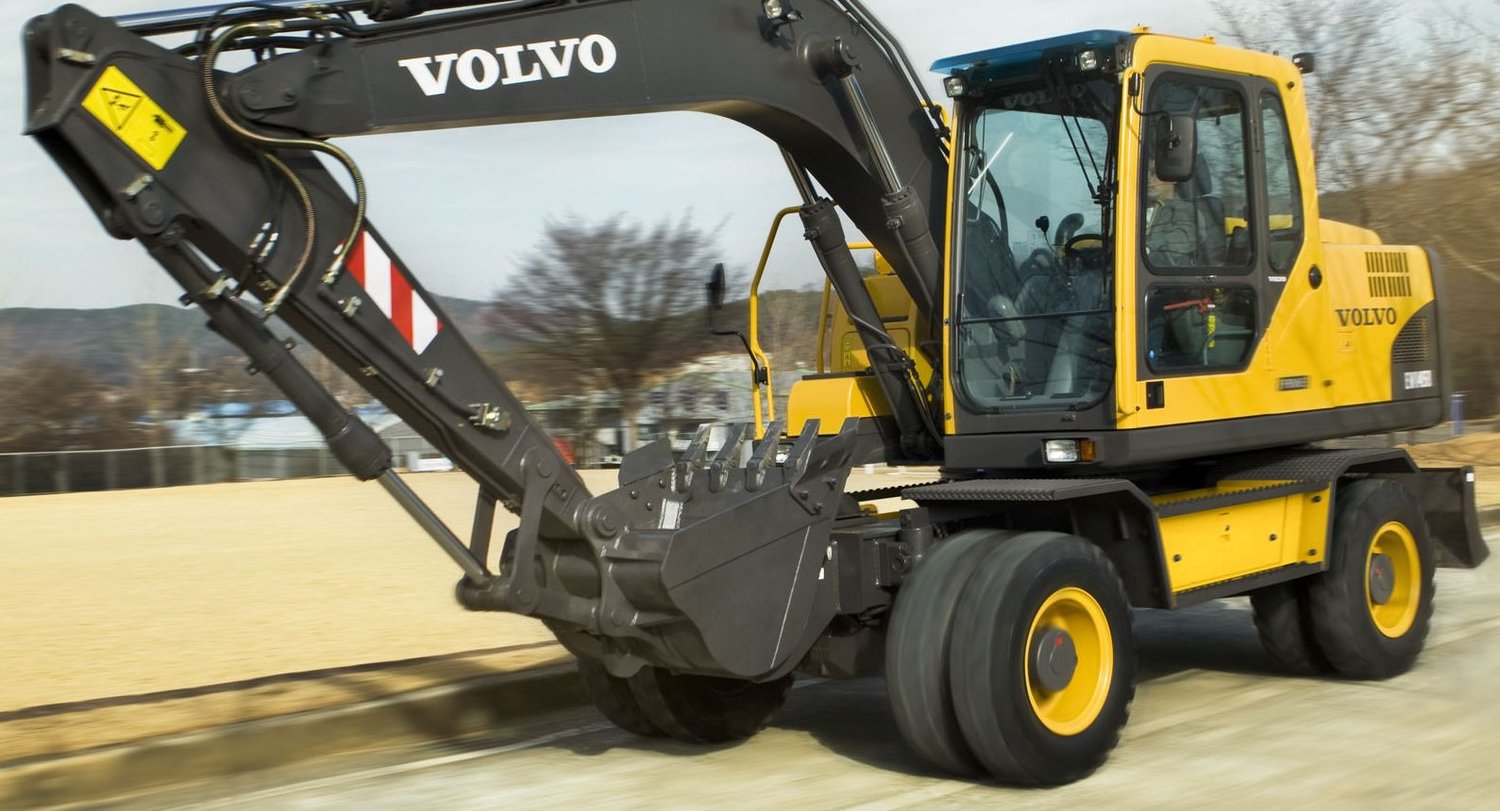
Volvo EW150C & Akerman EW150 Excavators Workshop Repair Manual PDF - MVOLCOEW150C.zip
EW150 Akerman, EW150C Volvo, EW150C Akerman Excavators Service Repair Manual.PDF
This is the full official service and repair manual, including Electrical Wiring Diagrams, for the EW150 Akerman, EW150C Volvo, and EW150C Akerman. It contains every piece of shop-level information needed to maintain, diagnose, and service these machines to professional mechanic standards.
EW150C Volvo series Excavators workshop service & repair manual includes:
* Numbered table of contents easy to use so that you can find the information you need fast.
* Detailed sub-steps expand on repair procedure information
* Numbered instructions guide you through every repair procedure step by step.
* Troubleshooting and electrical service procedures are combined with detailed wiring diagrams for ease of use.
* Notes, cautions and warnings throughout each chapter pinpoint critical information.
* Bold figure number help you quickly match illustrations with instructions.
* Detailed illustrations, drawings and photos guide you through every procedure.
* Enlarged inset helps you identify and examine parts in detail.
MAIN SECTIONS
0 - GENERAL
1 - STANDARD PARTS, SERVICE
2 - ENGINE WITH MOUNTING AND EQUIPMENT
3 - ELEC. SYSTEM; WARNING SYSTEM; INFORMATION SYSTEM; INSTRUMENTS
4 - POWER TRANSMISSION
5 - BRAKE
6 - STEERING
7 - FRAME; SPRINGS; DAMPING; AXLE SUSPENSION; WHEEL_TRACK UNIT
8 - MACHINERY HOUSE; CAB; EXTERIOR TRIM PARTS ANYWHERE
9 - HYDRAULIC SYSTEM; DIGGING_HANDLING_GRADING EQUIPM.; MISC EQUIPM
File Format: PDF (bookmarked, Searchable, Printable, high quality)
Language: English
Total Pages: 498 pages
TABLE OF CONTENTS - Expanded View
0 - GENERAL
00 - DESCRIPTION; COMPLETE MACHINE
Description of machine
Nameplates and their location
03 - SPECIFICATIONS
General_(0945)
Main dimensions
Tightening torque_(0921)
Weights_(0903)
05 - TRANSPORT, STORAGE, OPERATING INSTRUCTION
Transport data
Transporting the machine
1 - STANDARD PARTS, SERVICE
16 - LUBRICANT; FUEL; OTHER FLUID
Hydraulic oil – recommendations
17 - SERVICE
Connection_disconnection of vacuum pump – instructions
Dieseling in hydraulic cylinders
Electrical system – rules for work in the system
Jump-starting with a booster cable
Recommendations for cleanliness during hydraulic work
Shrinking – Instructions
Welding on the machine – instructions
19 - GENERAL
Charging of batteries
Fire protection
Handling of air conditioning
Handling of overheated Viton seals
Handling the counterweight
Pressure adjustment and leak detection
Safety during work with tyres
Safety
Service positions
Some simple safety rules for service
Work with painted surfaces and polymeric materials
2 - ENGINE WITH MOUNTING AND EQUIPMENT
21 - ENGINE
Diesel engine – description
General_(0259)
Rubber isolator for engine bracket – replacement
Weights_(0247)
22 - LUBRICATING SYSTEM
Refill capacities_(0212)
23 - FUEL SYSTEM
Fuelling pump – replacement
General_(0127)
Injection pump
Injector
Matarpump
Refill capacities_(0029)
26 - COOLING SYSTEM
Refill capacities_(5946)
V-belt – replacement
3 - ELECTRICAL; WARNING; INFORMATION; INSTRUMENTS
30 - GENERAL
Electrical components – location
General_(5829)
Main electrical units
Solenoid valves
31 - BATTERY
Batteries – overhaul
General_(5513)
32 - ALTERNATOR; CHARGE REGULATOR
Alternator – replacement
Charging system – overhaul
General_(5418)
33 - STARTING SYSTEM
Starter motor – replacement
37 - CABLE; FUSE; RELAY
Cable marking
Component list for diagram 10. Control equipment
Component list for diagram 11. Climate control equipment
Component list for diagram 1. Power supply equipm.
Component list for diagram 2. Monitoring equipm
Component list for diagram 3. Monitoring equipm
Component list for diagram 4. Service light equipm
Component list for diagram 5. Sundry equipment
Component list for diagram 6. Optional equipment
Component list for diagram 7. Cab equipment
Component list for diagram 8. Working light equipm
Component list for diagram 9. Control equipment
Electrical distribution box A2
Electric circuit diagrams and component lists – explanation key
Electric circuit diagrams – component lists and index
Fuse box A1 – main fuses F1–F15
Fuse box A1
38 - INSTRUMENT; SENSOR; WARNING & INFORMATION SYSTEM
ECU A3 – pins in connector
EDU A9 – pins in connection
Electronic Central Unit, ECU (A3)
Electronic Central Unit, ECU (A3) – replacement
Electronic Display Unit, EDU (A9)
Electronic Display Unit, EDU (A9) – replacement
Parameter codes A9
Parameter codes, alarm codes and error codes – presentation on display
Parameterkoder A3
Parameter programming
Trip switches and sensors
4 - POWER TRANSMISSION
41 - CLUTCH; TORQUE CONVERTER
Description_(3809)
43 - GEARBOX
Pump gearbox, shaft seal – replacement
Refill capacities_(3732)
44 - HYDROSTATIC DRIVE
Centre passage (9)
General_(3714)
Travel motor (4c)
Travel motor – replacement
46 - FRONT AXLE; REAR AXLE
Weights_(3414)
Weights_(3429)
49 - MISCELLANEOUS
Backlash in slewing system – measurement
Check values for end float in slew ring
Description_(3331)
Description of slewing brake
General_(3226)
Refill capacities
Slewing brake – replacement
Slewing drift – measurement
Slewing motor – replacement
5 - BRAKE
Automatic adjusting of drum brakes (front- and rear wheel brakes)
Control of gas pressure in brake accumulators for front and rear axle
Description of the brake system
6 - STEERING
Description of the steering system
Wheel steering valve (13j)
7 - FRAME; SPRINGS; DAMPING; AXLE SUSPENSION; WHEEL_TRACK UNIT
Counterweight – removal_fitting
Description_(3050)
General
Tightening torque
Weights
8 - MACHINERY HOUSE; CAB; EXTERIOR TRIM PARTS ANYWHERE
81 - CAB, NAKED; CANOPY
Cab – removal_fitting
Description
83 - DOORS; HATCH; COVER PLATE, (all)
Door catch – replacement
84 - TRIM PART; OUTSIDE; GLASS; SEALING MOULDING
Gas spring for window regulator – replacement
Upper windscreen – replacement
Window cassette in door – replacement
Window pane with moulding – replacement
87 - AIR CONDITIONING UNIT
Control valve, cab heater – replacement
Heater fan – replacement
9 - HYDRAULIC SYSTEM; DIGGING_HANDLING_GRADING EQUIPMENT; MISCELLANEOUS
91 - WORKING HYDRAULIC; SERVO HYDRAULICS
Circuit relief and refilling valve, 3b – circuit relief function
Circuit relief and refilling valve 3b – refilling
Control pressure for the digging and slewing movements – checking and adjustment
Control pressure valve for travel (12e) and brake (12f) plus the control valve (13i)
Control pressure valves (12a_b and 12c_d)
Control valve for digging brake (12p)
Description of hydraulic system
Directional control valve (5b, -d, -f, -h, -k) in main valve block
Float position valve 7a
General
Hose rupture valve (7c)
Hose rupture valve – renovation
Hose rupture valve – replacement
Hydraulic oil cooler (18d)
Hydraulic pressure – adjustment
Hydraulic pressure
Hydraullic oil tank (19c)
Insert in control pressure valve – renovation
Interconnection valve (7u)
Load-holding valve (8c)
Main valve block
P1 valve block (slewing valve block)
Pressure-limiting valve for servo pump (2d)
Pressure-limiting valves for P2 and P3 (2b and 2c)
Pump P1 – replacement
Pumps P2 and P3 – replacement
Refill capacities
right outrigger (12h)
Servo (1d) and steering pump (1e)
Servo pump – replacement
Shunt (7t) and pressure back-up valve (7d)
Undercarriage – hydraulics
Valve slide in main valve block – replacement of spring
Working pumps (1a-c)
97 - UNIT, DIGGING
boom cylinder – adjustment
Bucket cylinder – replacement
Description of moving functions in the hydraulic system
Digging equipment's hydraulic cylinders (6)
Dipper arm cylinder – replacement
Dipper arm – replacement
General
Hydraulic quickfit
Hydraulic quickfit – replacement of cylinder
Radial play in the digging equipment's pivot points – measurement
Shimming of the digging equipment pivot points – Instructions
Sink rate of digging equipment – measurement
Slewing pressure-limiting valve (2f)
Solenoid and shuttle valves
Tightening torque
Weights
99 - MISCELLANEOUS
Component list for hydraulic circuit diagrams
Hydraulic diagram
Markings in hydraulic system