
Caterpillar G3512 Generator Set Engine Workshop Repair Service Manual PDF - MCATG3512GEN.zip
A full factory-style service and repair guide, complete with electrical wiring diagrams, covering the Caterpillar G3512 Generator Set Engine — everything you need to service, troubleshoot, fix, and overhaul the engine just as a professional technician would.
Inside the Caterpillar G3512 Generator Set Engine workshop service and repair manual, you'll find:
* Numbered table of contents easy to use so that you can find the information you need fast.
* Detailed sub-steps expand on repair procedure information
* Numbered instructions guide you through every repair procedure step by step.
* Troubleshooting and electrical service procedures are combined with detailed wiring diagrams for ease of use.
* Notes, cautions and warnings throughout each chapter pinpoint critical information.
* Bold figure number help you quickly match illustrations with instructions.
* Detailed illustrations, drawings and photos guide you through every procedure.
* Enlarged inset helps you identify and examine parts in detail.
M0069850 - Disassembly and Assembly (G3512 Generator Set Engine).pdf
M0071734 - Troubleshooting (G3512 Generator Set Engines).pdf
M0071986 - Systems Operation (G3512 Generator Set Engines).pdf
M0071986 - Testing and Adjusting (G3512 Generator Set Engines).pdf
M0102167 - Schematic (G3512 Gas Engine Electrical System).pdf
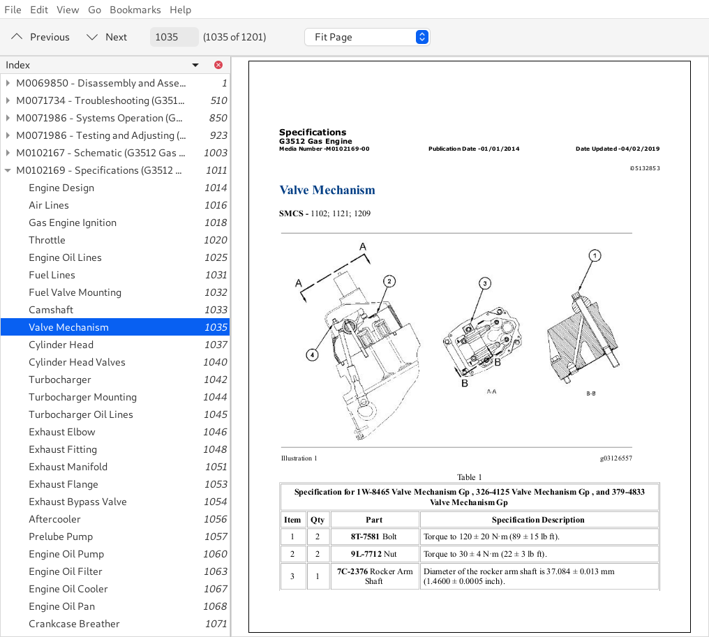
M0102169 - Specifications (G3512 Gas Engine).pdf
UENR7801 - Schematic (G3512 Standby Engine Electrical System).pdf
UENR7802 - Schematic (G3512 Standby Genset Electrical System).pdf
UENR7804 - Schematic (G3512A Generator Set Engine Electrical System).pdf
UENR8299 - Schematic (3500; C27; C32 and C175 Generator Set Modular Controls Electrical System).pdf
PRODUCT DETAILS:
Total Pages: 1,201 pages
File Format: PDF (Internal Links, Bookmarked, Table of Contents, Searchable, Printable, high quality)
Language: English
TABLE OF CONTENTS
M0069850 - Disassembly and Assembly (G3512 Generator Set Engine)...1
Electronic Control Module - Remove and Install...5
Gas Pressure Regulator Solenoid - Disassemble...8
Gas Pressure Regulator Solenoid - Assemble...10
Gas Pressure Regulator Solenoid - Remove and Install...12
Electric Starting Motor - Remove and Install...14
Inlet Manifold Pressure Sensor - Remove and Install...20
Inlet Manifold Temperature Sensor - Remove and Install...24
Alternator Mounting Group - Remove and Install...28
Alternator - Remove and Install...30
Crankcase Pressure Sensor - Remove and Install...33
Fuel Control Actuator - Remove and Install...37
Fuel Control Valve - Remove and Install...39
Throttle Control Valve - Remove...41
Throttle Control Valve - Install...43
Exhaust Elbow - Remove and Install...45
Exhaust Bypass - Remove and Install...48
Exhaust Manifold Shield - Remove and Install...50
Exhaust Manifold - Remove...60
Exhaust Manifold - Install...64
Exhaust Bypass Actuator - Remove and Install...69
Exhaust Temperature Sensor - Remove and Install - Left-Hand Turbocharger...71
Exhaust Temperature Sensor - Remove and Install - Right-Hand Turbocharger...74
Aftercooler - Disassemble...77
Aftercooler - Assemble...79
Aftercooler - Remove and Install...81
Air Inlet Manifold - Remove and Install...88
Turbocharger - Remove...99
Turbocharger - Install...102
Water Temperature Regulators - Remove...104
Water Temperature Regulators - Install...108
Thermostatic Valve - Remove...112
Thermostatic Valve - Disassemble...117
Thermostatic Valve - Assemble...119
Thermostatic Valve - Install...121
Water Pump - Remove...125
Water Pump - Disassemble...128
Water Pump - Assemble...134
Water Pump - Install...141
Auxiliary Water Pump - Remove...144
Auxiliary Water Pump - Disassemble...148
Auxiliary Water Pump - Assemble...153
Auxiliary Water Pump - Install...159
Coolant Temperature Sensor - Remove and Install...163
Engine Oil Pump - Remove...167
Engine Oil Pump - Disassemble...172
Engine Oil Pump - Assemble...176
Engine Oil Pump - Install...181
Engine Oil Cooler - Remove...186
Engine Oil Cooler - Disassemble...192
Engine Oil Cooler - Assemble...200
Engine Oil Cooler - Install...208
Engine Oil Pressure Sensor - Remove and Install - Unfiltered...214
Engine Oil Pressure Sensor - Remove and Install - Filtered...218
Engine Oil Temperature Sensor - Remove and Install...222
Engine Oil Filter Housing - Remove...226
Engine Oil Filter Housing - Disassemble...229
Engine Oil Filter Housing - Assemble...234
Engine Oil Filter Housing - Install...239
Engine Oil and Water Pump Drive - Remove...242
Engine Oil and Water Pump Drive - Disassemble...244
Engine Oil and Water Pump Drive - Assemble...247
Engine Oil and Water Pump Drive - Install...250
Engine Oil Pan - Remove...252
Engine Oil Pan - Disassemble...255
Engine Oil Pan - Assemble...258
Engine Oil Pan - Install...261
Engine Oil Sequence Valves - Remove and Install...263
Drive Housing (Front) - Remove and Install...268
Vibration Damper - Remove and Install...276
Flywheel - Remove and Install...287
Flywheel Housing - Remove...290
Flywheel Housing - Install...294
Crankshaft Front Seal and Wear Sleeve - Remove...299
Crankshaft Front Seal and Wear Sleeve - Install...301
Crankshaft Rear Seal and Wear Sleeve - Remove...308
Crankshaft Rear Seal and Wear Sleeve - Install...311
Engine Speed Sensor - Remove and Install...316
Accessory Drive (Front) - Remove...319
Accessory Drive (Front) - Disassemble...321
Accessory Drive (Front) - Assemble...324
Accessory Drive (Front) - Install...328
Gear Group (Rear) - Remove...330
Gear Group (Rear) - Install...333
Crankcase Breather - Remove and Install...339
Valve Cover and Spark Plug - Remove and Install...346
Rocker Shaft and Push Rod - Remove...351
Rocker Shaft - Disassemble...353
Rocker Shaft - Assemble...356
Rocker Shaft and Push Rod - Install...359
Detonation Sensor - Remove and Install...362
Camshaft Speed Sensor - Remove and Install...367
Cylinder Head - Remove...371
Cylinder Head - Disassemble...384
Cylinder Head - Assemble...389
Cylinder Head - Install...395
Piston Cooling Jets - Remove and Install...410
Bearing Clearance - Check...413
Connecting Rod Bearings - Remove and Install...416
Piston and Connecting Rods - Remove...421
Piston and Connecting Rods - Install...425
Cylinder Liner - Remove...429
Cylinder Liner - Install...431
Camshaft - Remove...435
Camshaft - Install...441
Camshaft Bearings - Remove...449
Camshaft Bearings - Install...452
Crankshaft Main Bearings - Remove...455
Crankshaft Main Bearings - Install...459
Crankshaft - Remove...463
Crankshaft - Install...467
Coolant Inlet Pressure Sensor - Remove and Install...473
Crankshaft Speed Sensor - Remove and Install...477
Throttle Differential Pressure Sensor - Remove and Install...481
Quick Start Gas Pressure Sensor - Remove and Install...484
Belt Guard - Remove and Install...488
Fan Drive - Remove and Install...499
M0071734 - Troubleshooting (G3512 Generator Set Engines)...510
General Information...513
Welding Precaution...514
Electronic Service Tools...516
System Overview...525
Component Location...528
Engine Monitoring System...529
Diagnostic Capabilities...543
Programmable Parameters...545
Electrical Connectors...546
Configuration Parameters...547
Diagnostic Trouble Codes...551
Event Codes...567
Symptom Troubleshooting...582
Alternator Problem - Charging Problem and_or Noisy Operation...584
Coolant Pressure Is Low...587
Coolant Temperature Is High...591
Coolant Temperature Is Low...597
Crankcase Pressure Is High...601
Crankcase Pressure Is Low...604
Detonation Occurrence...607
Engine Cranks but Does Not Start...615
Engine Does Not Crank...622
Engine Misfires; Runs Rough or Is Unstable...625
Engine Overloads...630
Engine Overspeeds...632
Engine Shutdown Occurrence...636
Engine Shutdown Occurs Intermittently...640
Engine Shutdown or Start Inhibit Initiated by Driven Equipment...643
Engine Stalls Immediately After Starting...645
Exhaust Temperature Is High...648
Exhaust Temperature Is Low...657
Fuel Differential Pressure Is High...664
Fuel Differential Pressure Is Low...666
Fuel Energy Content Problem...668
Fuel Pressure Is High...671
Fuel Pressure Is Low...673
Fuel Temperature Is High...676
Intake Manifold Air Temperature Is High...678
Oil Filter Differential Pressure Problem...684
Oil Pressure Is High...687
Oil Pressure Is Low...690
Oil Temperature Is High...695
Prelubrication Pump Problem...698
Temperature Ratio of Coolant to Oil Is Low...701
Data Link - Test...704
Data Link Configuration Status - Test...709
Detonation - Test...712
Electrical Power Supply - Test...720
Engine Control Switch - Test...724
Exhaust Temperature - Test...727
Fuel Metering Valve - Test - TecJet Valve...734
Fuel Shutoff - Test...739
Generator Output Power - Test...742
Ignition Primary - Test...745
Ignition Secondary - Test...755
Nitrogen Oxide Level - Test...765
Sensor Calibration Required - Test...771
Sensor Signal (Analog; Active) - Test...774
Sensor Signal (Analog; Passive) - Test...779
Sensor Supply - Test...783
Solenoid Valve - Test...789
Speed Control - Test...794
Speed_Timing - Test...802
Throttle Actuator - Test...808
Turbocharger Compressor Bypass - Test...813
Customer Passwords...817
Factory Passwords...819
ECM Will Not Accept Factory Passwords...821
Electronic Service Tool Does Not Communicate...823
Test ECM Mode...830
ECM Software - Install...832
ECM - Replace...834
Electrical Connectors - Inspect...836
Unburned Gas - Purge...845
Generator Output Power Sensor - Set...846
Timing - Calibrate...849
M0071986 - Systems Operation (G3512 Generator Set Engines)...850
Electronic Control System Operation...851
Electronic Control Module (ECM)...853
Start_Stop Control...854
Engine Governing...856
Electronic Control System Parameters - Configuration Parameters...857
Engine Monitoring System...872
Ignition System...874
Fuel System Operation...878
Air_Fuel Ratio Control - NOX Feedback...881
Aftercooler...885
Compressor Bypass...886
Exhaust Manifold...888
Turbocharger...889
Exhaust Bypass Valve...891
Valve System Components...893
Lubrication System...897
Cooling System...901
Cylinder Block; Liners and Heads...905
Pistons; Rings and Connecting Rods...908
Crankshaft...910
Camshaft...913
Electric Starting System...914
Power Supply...915
Grounding Practices...916
Alternator...917
Starting Solenoid...919
Starting Motor...921
M0071986 - Testing and Adjusting (G3512 Generator Set Engines)...923
General Information (Electronic Control System)...925
Engine Governing - Adjust...927
Manifold Air Pressure Sensor...930
Engine Speed_Timing Sensor...932
Ignition Timing - Adjust...934
General Information (Fuel System) - Gas...935
Air_Fuel Ratio Control - Adjust...936
Finding the Top Center Position for the No. 1 Piston...938
Camshaft Timing...940
Restriction of Air Inlet and Exhaust...946
Measuring Inlet Manifold Temperature...949
Measuring Exhaust Temperature...951
Exhaust Bypass Valve - Wastegate...952
Compression...954
Crankshaft Position for Valve Lash Setting...956
Valve Lash and Valve Bridge Adjustment...957
General Information (Lubrication System)...961
Excessive Bearing Wear - InspectExcessive Bearing Wear - Inspect...962
Excessive Engine Oil Consumption - Inspect...963
Increased Engine Oil Temperature - Inspect...964
Measuring Engine Oil Pressure...965
General Information (Cooling System)...967
Visual Inspection...969
Test Tools for the Cooling System...971
Testing the Cooling System...975
Cylinder Block...979
Cylinder Liner Projection...981
Flywheel - Inspect...986
Flywheel Housing - Inspect...990
Vibration Damper - Check...995
Test Tools for the Electrical System...997
Battery...1002
M0102167 - Schematic (G3512 Gas Engine Electrical System)...1003
Features...1003
Cover Page...1005
Schematic...1006
Machine Views...0
Control Box...1007
Left Side View...1008
Right Side View...1009
Top View...1010
M0102169 - Specifications (G3512 Gas Engine)...1011
Engine Design...1014
Air Lines...1016
Gas Engine Ignition...1018
Throttle...1020
Engine Oil Lines...1025
Fuel Lines...1031
Fuel Valve Mounting...1032
Camshaft...1033
Valve Mechanism...1035
Cylinder Head...1037