
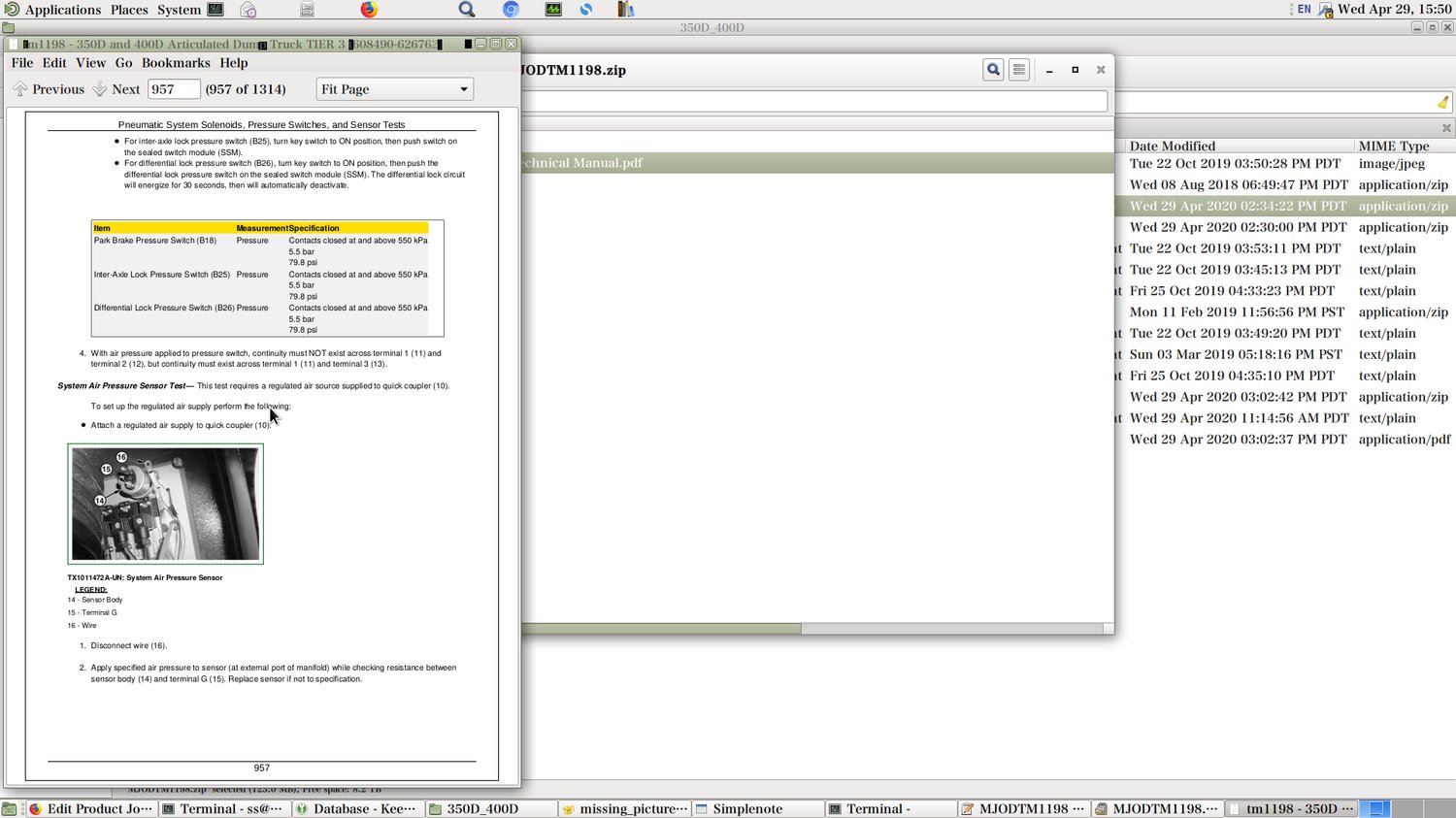
John Deere 350D & 400D Articulated Dump Truck Operation & Test Service Manual TM1198 PDF - MJODTM1198.zip
A full-service Diagnosis & Test guide featuring Electrical Wiring Diagrams covering John Deere Articulated Dump Trucks models 350D and 400D, packed with shop-level details to help you service, troubleshoot, fix, and rebuild your equipment the way expert technicians do.
Inside the John Deere 350D & 400D Articulated Dump Truck diagnostic workshop manual, you'll find:
* Numbered table of contents easy to use so that you can find the information you need fast.
* Detailed sub-steps expand on repair procedure information
* Numbered instructions guide you through every repair procedure step by step.
* Troubleshooting and electrical service procedures are combined with detailed wiring diagrams for ease of use.
* Notes, cautions and warnings throughout each chapter pinpoint critical information.
* Bold figure number help you quickly match illustrations with instructions.
* Detailed illustrations, drawings and photos guide you through every procedure.
* Enlarged inset helps you identify and examine parts in detail.
(SN. 608490-626762)
350D (SN. 608490-626762)
400D (SN. 608490-626762)
TM1198 - John Deere 350D, 400D Articulated Dump Truck Technical Manual - Operation & Test.PDF
TM1198 - John Deere 350D, 400D Articulated Dump Truck Technical Manual - Operation & Test.epub
Total Pages: 1,314 pages
File Format: PDF (bookmarked, ToC, Searchable, Printable, high quality)
Language: English
MAIN SECTIONS
Foreword
Technical Information Feedback Form
General Information
Safety
Diagnostic Trouble Codes (DTC)
Chassis Control Unit (CCU) Diagnostic Trouble Codes
Engine Control Unit (ECU) Diagnostic Trouble Codes
Electronic Unit Injector (EUI) Controller Diagnostic Trouble Codes
Monitor Display Unit (MDU) Diagnostic Trouble Codes
Output Expansion Unit (OEU) Diagnostic Trouble Codes
Sealed Switch Module (SSM) Diagnostic Trouble Codes
Transmission Control Unit (TCU) Diagnostic Trouble Codes
Operational Checkout Procedure
Operational Checkout Procedure
Engine
Theory of Operation
Diagnose Engine Malfunctions
Adjustments
Tests
Electrical System
System Information
System Diagrams
Sub-System Diagnostics
References
Power Train
Theory of Operation
Diagnostic Information
Tests
Pneumatic System
Theory of Operation
Diagnostic Information
Tests
Hydraulic System
Theory of Operation
Diagnostic Information
Tests
Heating and Air Conditioning
Theory of Operation
Diagnostic Information
Tests
tm1198 - 350D and 400D Articulated Dump Truck TIER 3(608490-626762)
Table of Contents
Foreword
Technical Information Feedback Form
Section 9000: General Information
Group 01: Safety
Recognize Safety Information
Follow Safety Instructions
Operate Only If Qualified
Wear Protective Equipment
Avoid Unauthorized Machine Modifications
Inspect Machine
Stay Clear of Moving Parts
Avoid High-Pressure Fluids
Avoid High-Pressure Oils
Beware of Exhaust Fumes
Prevent Fires
Prevent Battery Explosions
Handle Chemical Products Safely
Dispose of Waste Properly
Prepare for Emergencies
Use Steps and Handholds Correctly
Start Only From Operator's Seat
Use and Maintain Seat Belt
Prevent Unintended Machine Movement
Avoid Work Site Hazards
Keep Riders Off Machine
Avoid Backover Accidents
Avoid Machine Tip Over
Operating on Slopes
Operating or Traveling on Public Roads
Inspect and Maintain ROPS
Add and Operate Attachments Safely
Park and Prepare for Service Safely
Service Tires Safely
Service Cooling System Safely
Remove Paint Before Welding or Heating
Make Welding Repairs Safely
Drive Metal Pins Safely
Section 9001: Diagnostic Trouble Codes (DTC)
Group 10: Chassis Control Unit (CCU) Diagnostic Trouble Codes
Diagnostic Trouble Code (DTC) Quick Reference List—Chassis Control Unit (CCU)
000097.03 - Water In Fuel Voltage Out of Range High
000097.04 - Water In Fuel Voltage Out of Range Low
000097.16 - Water In Fuel Detected
008000.05 - Headlight Dip Open Circuit
008000.06 - Headlight Dip Short Circuit
008000.18 - Headlight Dip Less than Normal Current
008001.05 - Headlight Bright Open Circuit
008001.06 - Headlight Bright Short Circuit
008001.18 - Headlight Brights Less than Normal Current
008002.00 - System Air Pressure Voltage Too High
008002.01 - System Air Pressure Voltage Too Low
008003.00 - Start Signal Voltage Too High
008004.05 - Reverse Open Circuit
008004.06 - Reverse Short Circuit
008004.18 - Reverse Less Than Normal Current
008005.00 - Rear Two Speed Switch Voltage Too High
008006.00 - Middle Two Speed Switch
008007.05 - Rear Wiper LO Speed Open Circuit
008007.06 - Rear Wiper LO Speed Short Circuit
008007.18 - Rear Wiper Lo Speed Less Than Normal Current
008008.00 - Scraper Dash Switch Voltage Too High
008009.01 - Pressure Two Speed Switch Voltage Too High
008010.05 - Front Wiper LO Speed Open Circuit
008010.06 - Front Wiper LO Speed Short Circuit
008010.18 - Front Wiper Lo Speed Less Than Normal Current
008011.00 - Battery Voltage Too High
008011.01 - Battery Voltage Too Low
008012.00 - Horn Switch Voltage Too High
008013.05 - Park Lights Open Circuit
008013.06 - Park Lights Short Circuit
008013.18 - Park Lights Less than Normal Current
008014.01 - Ignition Supply via Fuse 25 Voltage Too Low
008015.05 - Work Lights Open Circuit
008015.06 - Work Lights Short Circuit
008015.18 - Work Lights Less than Normal Current
008016.01 - Ignition Supply via Fuse 26 Voltage Too Low
008017.01 - Brake Light Switch Voltage Too Low
008018.03 - IDL Solenoid or Bin Pressure Reduction Solenoid Voltage Too High
008018.05 - IDL Solenoid or Bin Pressure Reduction Solenoid Open Circuit or Short Circuit
008019.00 - Bonnet Fan Temp Switch Voltage Too High
008021.00 - Left Height Position Sensor Voltage Too High
008021.01 - Left Height Position Sensor Voltage Too Low
008022.01 - Hazard Dash Switch Voltage Too Low
008023.00 - Right Height Position Sensor Voltage Too High
008023.01 - Right Height Position Sensor Voltage Low
008024.03 - Bin Lever Latch or Pneumatic Blow Off Solenoid Voltage Too High
008024.05 - Bin Lever Latch or Pneumatic Blow Off Solenoid Voltage Too Low
008025.00 - Artic Angle Position Sensor Voltage Too High
008025.01 - Artic Angle Position Sensor Voltage Too Low
008026.00 - Bin Position Sensor Voltage Too High
008026.01 - Bin Position Sensor Voltage Too Low
008026.02 - Bin Position Sensor Voltage Erratic
008027.03 - CTD Solenoid or Rear Wiper High Speed Voltage Too High
008027.05 - CTD Solenoid or Rear Wiper High Speed Open Circuit or Short Circuit
008028.00 - Bin Lever Position Sensor Voltage Too High
008028.01 - Bin Lever Position Sensor Voltage Too Low
008030.01 - Park Brake Dash Switch Voltage Too Low
008031.00 - Front Two Speed Switch Voltage Too High
008032.03 - Flashing Beacon Light or Horn Voltage Too High
008032.05 - Flashing Beacon Light or Horn Open Circuit or Short Circuit
008033.00 - Aircon Evaporator Temperature Voltage Too High
008033.01 - Aircon Evaporator Temperature Voltage Too Low
008034.00 - Wet Disk Brake Temperature Voltage Too High
008034.01 - Wet Disk Brake Temperature Voltage Too Low
008035.00 - Cab Temperature Voltage Too High
008035.01 - Cab Temperature Voltage Too Low
008036.00 - 5-Volt Supply to Bin and Articulation Position Sensors Too High
008036.01 - 5-Volt Supply to Bin and Articulation Position Sensors Too High
008037.00 - 5-Volt Supply to Bin Sensors Too High
008037.01 - 5-Volt Supply to Bin Sensors Too Low
008038.01 - Ignition Power via Fuse 27 Voltage Too Low
008039.01 - Ignition Power via Fuse 28 Voltage Too Low
008040.00 - Alternator Voltage via Fuse 29 Too High
008040.01 - Alternator Voltage via Fuse 29 Too Low
008040.17 - Battery Voltage Too Low
008041.03 - Artic Reverse Light or Rear Washer Pump Voltage Too High
008041.05 - Artic Reverse Light or Rear Washer Pump Open Circuit or Short Circuit
008042.03 - Recirculation Flap or Aircon Clutch Solenoid Voltage Too High
008042.05 - Recirculation Flap or Aircon Clutch Solenoid Open Circuit or Short Circuit
008043.05 - Bin Up Solenoid Open Circuit
008043.06 - Bin Up Solenoid Short Circuit
008044.03 - Engine Running or Brake Light Output Voltage Too High
008044.05 - Engine Running or Brake Light Open Circuit or Short Circuit
008045.03 - Left Indicator Light or Right Indicator Light Voltage Too High
008045.05 - Left Indicator Light or Right Indicator Light Open Circuit
008046.03 - Front Wiper Hi Speed or Front Washer Pump Voltage Too High
008046.05 - Front Wiper Hi Speed or Front Washer Pump Open Circuit or Short Circuit
008047.03 - Mirror Heating or Hydraulic Cut Solenoid Voltage Too High
008047.05 - Mirror Heating or Hydraulic Cut Solenoid Open Circuit
008048.03 - Bin Down Solenoid Open Circuit
008048.05 - Bin Down Solenoid Short Circuit
008048.06 - Bin Down Solenoid Short to Ground
008049.03 - Overspeed Control or Park Brake Solenoid Voltage Too High
008049.05 - Overspeed Control or Park Brake Solenoid Open Circuit or Short Circuit
008050.00 - Hydraulic Temperature Sensor Voltage Too High
008050.01 - Hydraulic Temperature Sensor Voltage Too Low
008051.01 - Ignition Power Voltage via Fuse 30 Too Low
008052.01 - Ignition Power Voltage via Fuse 31 Too Low
008100.31 - Boost Pressure Protection Is Activated
008101.31 - Free Wheeling Event Detected
008102.31 - Engine is Idling for More than 20 Minutes
008103.31 - Engine RPM Exceeded Allowable Limit
008104.31 - Output Shaft Speed Exceeded Allowable Limit
008105.31 - Bin (Dump Body) Overload
008106.31 - Harsh Braking Detected
008107.31 - Engine Coolant Temperature Too High
008108.31 - Engine Oil Pressure Too Low
008109.31 - Transmission Sump Temperature Too High
008110.31 - TCU Calibration Mismatch
008111.31 - Park Brake Burnout Event Detected
008113.31 - Hydraulic Temperature Too High
008114.31 - Wet Disk Brake Temperature Too High
008116.31 - Tire Speed Limitation Exceeded
008119.31 - Unexpected Bin (Dump Body) Direction
Group 20: Engine Control Unit (ECU) Diagnostic Trouble Codes
Diagnostic Trouble Code (DTC) Quick Reference List—Engine Control Unit (ECU)
000045.03 - Constant Throttle (EVB) Open Circuit
000045.04 - Constant Throttle (EVB) Closed Circuit
000084.03 - Tachometer Signal Open Circuit
000084.04 - Tachometer Signal Short Circuit
000084.14 - Tachometer Signal Not Recognized
000098.00 - Oil Level Too High
000098.01 - Oil Level Too Low
000098.14 - Oil Level Very Low—Dangerous
000100.01 - Low Oil Pressure
000100.14 - Oil Pressure Very Low
000107.00 - Air Filter Sensor Air Pressure Too High
000107.03 - Air Filter Sensor Open Circuit
000107.04 - Air Filter Sensor Short Circuit
000110.00 - Coolant Temperature High
000110.14 - Coolant Temperature Dangerously High
000111.01 - Engine Coolant Level Low
000111.03 - Engine Coolant Level Sensor Open Circuit
000111.04 - Engine Coolant Level Sensor Short Circuit
000158.00 - Ignition Volts Too High
000158.01 - Ignition Volts Too Low
000558.05 - Pedal Switches Open
000558.12 - Pedal Switches Closed
000625.02 - CAN Error No Connection Between ECU and EUI
000625.14 - CAN Error Single Wire Connection Between ECU and EUI
000629.12 - ECU Internal Failure
000639.2 - CAN Identifiers Missing
000677.05 - Control Relay 1 Open Circuit
000677.06 - Control Relay 1 Short Circuit
000730.00 - Control Relay 2 Heat Exchanger No Increase In Intake Manifold Air Temperature
000730.01 - Control Relay 2 Heat Exchanger Contacts Sticking
000730.02 - Control Relay 2 Heat Exchanger Contacts Not Closing
000730.03 - Control Relay 2 Heat Exchanger Voltage Too High or Shorted To Battery Voltage
000730.04 - Control Relay 2 Heat Exchanger Voltage Too Low or Shorted To Ground
001004.03 - Control Relay 4 Open Circuit
001004.04 - Control Relay 4 Short Circuit
001005.03 - Pulse Width Modulation Accelerator Pedal Supply Voltage Open Circuit
001005.04 - Pulse Width Modulation Accelerator Pedal (PWM) Supply Voltage Short to Ground
001006.03 - Exhaust Brake Open Circuit
001006.04 - Exhaust Brake Short to Ground
001015.01 - Pulse Width Modulation Accelerator Pedal No Input Voltage
001015.02 - Pulse Width Modulation Accelerator Pedal (PWM) Both Signals Missing
001015.03 - Pulse Width Modulation Accelerator Pedal (PWM) Signal 2 Missing
001015.04 - Pulse Width Modulation Accelerator Pedal (PWM) Signal 1 Missing
001015.05 - Pulse Width Modulation Accelerator Pedal (PWM) Not Been Set or Programmed
001015.06 - Pulse Width Modulation Accelerator Pedal (PWM) Idle Not Been Set or Programmed
001015.07 - Pulse Width Modulation Accelerator Pedal (PWM) High Idle Not Set or Programmed
Group 30: Electronic Unit Injector (EUI) Controller Diagnostic Trouble Codes
Diagnostic Trouble Code (DTC) Quick Reference List—Electronic Unit Injector (EUI) Controller
000094.02 - Fuel Pressure Sender Value Not Recognized
000094.03 - Fuel Pressure Sender Voltage Too High or Short to Positive
000094.04 - Fuel Pressure Sender Voltage Too Low or Short to Ground
000098.02 - Engine Oil Level Incorrect or Sensor Defective
000098.03 - Engine Oil Level Sender Out of Range High
000098.04 - Engine Oil Level Sender Out of Range Low
000098.05 - Engine Oil Level Sender Open Circuit
000100.02 - Engine Oil Pressure Sender Value Not Recognized
000100.03 - Engine Oil Pressure Sensor Out of Range High
000100.04 - Engine Oil Pressure Sensor Out of Range Low
000102.01 - Charge Air Boost Path Circuit
000102.02 - Charge Air Pressure Sender Value Not Recognized
000102.03 - Intake Pressure Sensor Range Too High
000102.04 - Intake Pressure Sensor Range Too Low
000105.00 - Manifold Air Temperature Extremely High
000105.03 - Charge Air Temperature Sender Out of Range High
000105.04 - Charge Air Temperature Sender Out of Range Low
000110.03 - Coolant Temperature Sender Out of Range High
000110.04 - Coolant Temperature Sensor Range Too Low
000158.02 - Ignition Supply Not Constant between ECU and EUI
000168.03 - Input Voltage Too High
000168.04 - Input Voltage Too Low
000174.03 - Fuel Temperature Sender Out of Range High
000174.04 - Fuel Temperature Sender Out of Range Low
000175.03 - Engine Oil Temperature Sender Out of Range High
000175.04 - Engine Oil Temperature Sender Out of Range Low
000190.00 - Engine RPM Out of Range High
000609.02 - EUI Controller Internal Failure
000609.12 - EUI Controller Internal Failure
000609.14 - Internal Failure EUI Controller
000625.02 - CAN Failure
000625.14 - Controller Area Network (CAN) Failure
000636.01 - Crankshaft Sender Gap Too Small
000636.03 - Crankshaft Sender Open Circuit
000636.04 - Crankshaft Sender Short to Ground