
Deutz-Fahr AGROPLUS 75 85 95 100 Tractor Workshop Repair Service Manual PDF - MDFAP75AP100OPEK.zip
A full workshop manual covering electrical wiring schematics for the Deutz-Fahr AGROPLUS 75, AGROPLUS 85, AGROPLUS 95, and AGROPLUS 100 tractors — everything needed to service, troubleshoot, fix, and rebuild these machines to a professional mechanic's standard.
This Deutz-Fahr AGROPLUS 75, AGROPLUS 85, AGROPLUS 95, and AGROPLUS 100 tractor workshop service and repair manual contains:
* Numbered table of contents easy to use so that you can find the information you need fast.
* Detailed sub-steps expand on repair procedure information
* Numbered instructions guide you through every repair procedure step by step.
* Troubleshooting and electrical service procedures are combined with detailed wiring diagrams for ease of use.
* Notes, cautions and warnings throughout each chapter pinpoint critical information.
* Bold figure number help you quickly match illustrations with instructions.
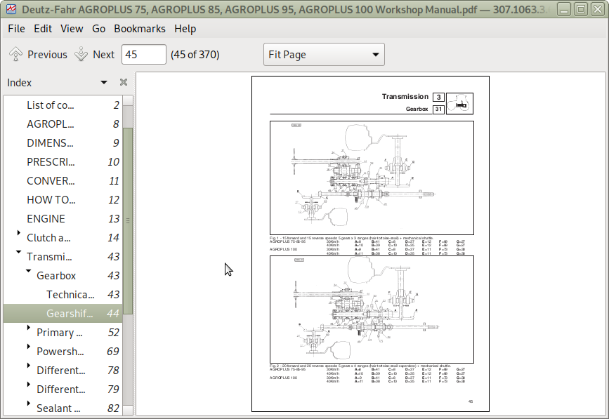
* Detailed illustrations, drawings and photos guide you through every procedure.
* Enlarged inset helps you identify and examine parts in detail.
Deutz-Fahr AGROPLUS 75, AGROPLUS 85, AGROPLUS 95, AGROPLUS 100 Workshop Manual.pdf
Total Pages: 370 pages
File Format: PDF (bookmarked, Searchable, Printable, high quality)
Language: English
TABLE OF CONTENTS
Agroplus 75 - 85 - 95 - 100 tractor configurations · 8
Dimensions and weights · · 9
Prescribed Lubricant and fuels · · 10
Conversion tables· 11
Parts· 12
1 - ENGINE
• Engine · 13
2 - CLUTCH AND TRANSMISSION
• Gearshift clutch · · 14
• General characteristics · 14
• Technical specifications · · 14
• Installation of the clutch release fork · · 19
• Cecking clutch · 20
• Adjusting clutch control pedal · 20
• Bleeding air from the hydraulic circuit · 20
• Stripping the slave cylinder · 21
• Inspections · · 21
• Notes on refitment · · 21
• Stripping the master cylinder · · 22
• Inspections and checks · · 23
• Reassembly · 23
• Fault diagnosis· 24
• Powershift unit · 25
• Technical specifications · · 25
• Fitment of the Powershift unit · 29
• Adjustment of end float in the Powershift unit · 31
• Main operazions involved in assembly of Powershift unit · · 32
• Spring specifications · · 42
• Fault diagnosis· 42
3 - TRANSMISSION
Technical specifications · · 43
Transmission configurations with 5 speed gearbox · 44
Gearbox removal · 59
Stripping the gearbox· · 60
Examining parts removed · · 61
• Gearbox case · · 61
• Shafts · · 61
• Gears · · 61
• Synchronizers · · 61
• Bearings · · 61
• Installing circlips of variable thickness · 62
• Nominal dimensions of gearbox bushes· · 62
• Installing the intermediate shaft bearing · · 63
• Adjusting secondary shaft end float for the 5-speed gearbox· · 64
Shimming the range gear input shaft on tractors without Powershift transmission · 65
• Calculating shim thickness · · 66
Shimming the range gear input shaft on tractors with Powershift transmission· · 67
• Calculating shim thickness · · 68
“Powershuttle” electro-hidraulic shuttle control · · 69
• Updating the EPROM of the Control unit · 69
• Powershuttle self-diagnostics tester · 71
• Installation of the shuttle unit · · 75
• Assembly of the compound gears· 76
Adjustment of the shuttle unit · · 76
Adjusting the bevel drive · 78
Refitting the bevel drive without replacing any components · · 78
Replacing the crown wheel bearings · · 78
Replacing the pinion bearings · 78
Installation of the support plate for the gear selector rods · · 80
Orienting the gearbox shuttle control levers · · 81
Surfaces where sealant is to be applied · 82
Main assembly operations involving transmission housing, rear axle, hydraulic lift
and engine · · 88
Tightening torques · · 92
Rear power take-off · 94
Operation of Power take-off - Agroplus 75 - 85 - 95 (4 speeds) · · 99
Operation of Power take-off - Agroplus 100 (4 speeds) · 100
Technical specifications · 101
Fitting the P.T.O. shaft · · 101
Power take-off clutch · 102
Spring specifications · 102
Checking end float on the front shaft of the P.T.O. clutch · 104
Checking the clearance between discs · 106
Testing pressures in the clutch assembly· · 107
Essential operations for refitment of the rear P.T.O. assembly · 109
Fault diagnosis · · 111
4 - DRIVE AXLES - AXLES
Rear axle · · 112
Assembly of rear halfshafts · · 115
Removing and stripping the epicyclic hub assembly · 117
2-W.D. extendible axle · · 118
Removing the axle from the front support · 120
Centre steering lever · 123
Wheel hub · 124
Inspections and checks · 125
• Correct steering rod assembly · · 126
• Adjusting end play· · 126
Front-wheel drive · · 127
• Technical specifications · 127
• Front drive axle ratios · 127
• Adjusting toe-in · · 127
• Adjusting steering angles · · 127
• Inspections and checks · · 129
Wheel hub · 130
Final epicyclic reducer · · 131
• Disassembling the hub · · 131
• Stripping down the epicyclic · · 131
• Installation · · 131
• Shimming epicyclic reducer bearings · 131
• Brakes· 132
• Final epicyclic reducer · · 132
• Axle shafts · 132
• Forks · · 132
• Adjusting wheel fork bearing preloading · 132
Side hubs · · 133
Fitting the bolts and pivots of the steering cylinder mounting · · 134
Pins · · 134
Axle shafts · 134
Gears · 134
Bearings· 134
Adjusting bevel gears· 136
Internal adjustment of mechanical type differential lock· 137
Installing the differential assembly into the drive axle · · 137
Tightening torques · 138
Fitting the steering angle limiting bolts· · 138
Fault diagnosis· · 140
ASM System · 141
General characteristics · 141
Setting the angle of the ASM sensor positioning plate · 142
Fitting the steering angle sensor · · 142
Removing the differential unit from the front axle· · 143
Stripping the front differential lock clutch · · 143
adjustment of front axle bevel gear pair on machines with ASM System · 144
Installation of differential unit in front axle · 146
Assembly and positioning of the ASM System brake switches · 146
Four wheel drive engagement clutches for machines with ASM System· · 147
Technical specifications · 147
Front and rear differential lock clutches for machines with ASM System · 148
Technical specifications · 148
5 - VEHICLE
• Brakes · · 149
• General characteristics · · 149
• Technical specifications · 149
• Hydraulic pump · 150
• Disassebly and checking procedure · · 150
• Assembly of brake master cylinder · · 152
• Checking the discs of the 2WD and 4WD front brakes and rear brakes · · 153
• Adjusting service brake pedals · 153
• Checking parking brake pads · · 154
• Parking brake control lever overall travel · · 154
• Bleeding air from the brake hydraulic system · · 155
• “Separate Brakes” valve · · 156
• Fault diagnosis· · 160
• Technical specifications · 161
• Electronic power-lift · · 162
• Electronic control unit: operator panel · · 162
• Operation · · 165
• Main control switch · 165
• Stop switch · 165
• ALL ROUND TESTER (1st version)· · 166
• Resident diagnostics · 171
• AUTO-MAN procedure for entering the wheel constant relative to a tyre not listed in the table · 175
• Setting the maximum lift height· · 175
Setting up the draft control sensor · 175
Setting up the steering sensor · · 176
Verify the operational efficiency of the system's electrical components · 176
Multifunction control handset mounted to seat armrest · 176
External buttons · 176
Position control sensor· · 176
ASM System · 176
Selecting the control type· · 177
Setting the maximum lift height · 177
Lock/Unlock pushbutton· 177
Ground-operated pushbutton controls · · 178
Main control knob · · 178
Lowering speed adjustment knob · 178
Sensitivity adjustment knob · · 178
Up/Down indicator lights · · 178
Alarm warning light · · 178
Electronic lift type ELCII· 179
Control panel · 180
Lift operating controls· 181
Lift setting controls · 182
Safety features· · 182
Oscillation damping during transport · 183
Operating conditions · 183
Auxiliary service control switches· · 183
Procedure for setting up the electronic lift · 184
RADAR / No RADAR · 184
Entering the type of tyre· 184
ALL ROUND TESTER (2nd version) · 186
Emergency manual control of the electronic lift · 192
Solenoid operated control valve, hydraulic lift · · 193
Control of lift system operating pressure · · 194
Electro-hydraulic power-lift distributor · · 195
Fitment of lift arms position control sensor· 201
Operation of the directional control solenoid valves · 201
Correct fitment of draft control sensor · · 204
Onboard radar · · 205
Electronic power-lift safety precautions · 205
How an electronic system must be inspected · · 206
Checking mechanical parts · · 206
Fitting the lift arms cross shaft crank lever set screw· 206
Original type "load sensing" hydraulic power-lift · · 208
• Controls· · 208
• Fitment of cross shaft crank lever set screw · · 211
• Fitment of cross shaft cam set screw · 211
• Fitment of piston seal · 211
• Adjusting power-lift system · 218
• Adjusting lifting control lever · · 218
• Adjusting working depth control lever · 218
• Checking the lifting system · 221
• Checking the operating pressure of the lift system · 221
• Removing the directional control valve from the lift housing · · 221
• Checking distributor when assembled · · 222
• Inspection and checks · · 224
• Reassembling the lift · · 224
Sensing arm· · 225
• Power-lift distributor valve spring setting specifications · 228
• Fault diagnosis · · 229
Front hydraulic power-lift · · 230
• Inspections · 230
• Technical specifications · 231
• Hydraulic pressure accumulator and anti-shock valve for the front power-lift · 231
Front power take-off· · 233
• General characteristics · · 233
• Technical data · 233
• Engagement stage · 234
• Disengagement stage · 235
• Checking clutch· · 239
• Check the clearance of the clutch friction discs · 239
Checking the clutch assembly engagement pressure · · 239
• With the P.T.O. engaged · 239
• With the P.T.O. disengaged· 239
Fault diagnosis· · 240
Spring specifications · 240
6 - CONTROLS
• Hydrostatic steering · ·
• General characteristics · ·
• Inspections and checks ·
• Steering pump·
• Directional control valve ·
• Check the setting of the pressure relief valve ·
• Bleeding the hydraulic circuit ·
• Assembly of orbital pump unit·
• Steering wheel shaft · ·
• Steering cylinders · ·
• Servicing · ·
• Instructions for the hydrostatic steering distributor assembly · ·
• Mechanical controls · ·
• Fitting and adjustment of the external controls of the mechanical governor ·
• Accelerator pedal · ·
• Hand throttle · ·
• Connection of the accelerator pedal and hand throttle cables to the governor· ·
• Electrohydraulic controls · ·
Front PTO clutch command · · 262
Rear PTO clutch command· 262
ASM System control · · 262
HARD/SOFT gearshift control· 262
Differential lock engagement control· · 262
Front-wheel drive engagement · · 262
PTO control· 262
Transmission· · 262
“Powershuttle” with electro-hydraulic control · 262
Front and rear lift· 262
Rear differential lock control cylinder for machines not equipped with ASM System· 274
Four wheel drive disengagement cylinder for machines not equipped with
ASM System · 274
Adjustment of front and rear differential lock control mechanism for machines not
equipped with ASM System · · 275
Adjustment of four wheel drive control linkage for machines not equipped with
ASM System · 276
7 - BODY
• Platform · 277
• Cab · · 278
• General characteristics · · 278
• Cab air filter · · 280
• Screen wash · 280
• Screen wipers (front and rear) · · 280
• Removing the driving platform complete with cab · 281
• Remove cab· · 282
8 - SYSTEMS
Ventilation · 283
Heating System · 283
System configuration · 284
Air conditioning unit for cabs · 287
Operation and maintenance of the air-conditioning system · · 288
• Air-conditioning process · 288
• How to operate the system · 288
• Checking the air-conditioning system charge · 288
• Electric fan unit · · 289
• Tracing faults in the electric fan unit · · 289
Checking system · · 291
System safety elements· 291
• Minimum pressure switch · · 291