
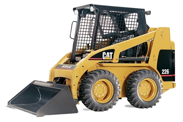
Caterpillar 216 226 228 232 236 242 247 248 252 262 267 277 287 Skid Steer Loader Workshop Repair Service Manual PDF - MCAT216287OPEK.zip
A full-service repair guide, complete with electrical wiring diagrams, covering the Caterpillar Loaders 216, 226, 228, 232, 236, 242, 247, 248, 252, 262, 267, 277 and 287. It delivers the same workshop-level knowledge professionals rely on to keep these machines maintained, troubleshoot faults, and carry out repairs and servicing.
Inside, the Caterpillar Loaders 216, 226, 228, 232, 236, 242, 247, 248, 252, 262, 267, 277, 287 workshop service repair manual provides:
* Numbered table of contents easy to use so that you can find the information you need fast.
* Detailed sub-steps expand on repair procedure information
* Numbered instructions guide you through every repair procedure step by step.
* Troubleshooting and electrical service procedures are combined with detailed wiring diagrams for ease of use.
* Notes, cautions and warnings throughout each chapter pinpoint critical information.
* Bold figure number help you quickly match illustrations with instructions.
* Detailed illustrations, drawings and photos guide you through every procedure.
* Enlarged inset helps you identify and examine parts in detail.
PRODUCT DETAILS:
Total Pages: 1,330 pages
File Format: PDF (bookmarked, Searchable, Printable, high quality)
Language: English
Table of Contents
The order of grouping is as follows: Systems Operation, Testing and Adjusting, Troubleshooting, Specifications / Disassembly and Assembly.
Air Inlet And Exhaust System
Basic Engine
Cooling System
Electrical And Starting System
Engine Arrangement
Frame And Body
Fuel System
Hydraulic System
Implements
Lubrication System
Machine Arrangement
Operator Station
Power Train
Service Equipment And Supplies
Torque Specifications
Work Tools
Electrical Schematic
Hydraulic Schematic
RENR2857 - Disassembly and Assembly (216, 226 and 228 Skid Steer Loaders Powertrain)....3
Axle - Assemble....4
Axle - Disassemble....9
Axle - Install....14
Axle - Remove....16
Chain (Drive) - Remove and Install....20
Chain (Drive) Tension - Adjust....22
Hydraulic Filter - Remove and Install....26
Hydraulic System Pressure - Release....32
Piston Motor (Hydrostatic) - Remove and Install....34
Piston Pump (Hydrostatic) - Install....40
Piston Pump (Hydrostatic) - Remove....46
Sprocket (Axle) - Install....52
Sprocket (Axle) - Remove....61
Sprocket (Motor) - Install....65
Sprocket (Motor) - Remove....72
Tire and Rim - Remove and Install....81
RENR2858 - Specifications (216, 226 and 228 Skid Steer Loaders Machine Systems)....85
Axle....86
Bank Valve....88
Engine Enclosure....102
Gas Spring (Cab)....104
Gear Motor (Fan)....108
Gear Pump....110
Hydraulic Oil Filter....125
Hydraulic Tank....128
Interlock Manifold Valve and Mounting....131
Lift Cylinder....133
Loader Frame....135
Motor Mounting (Hydrostatic)....138
Pilot Operated Hydraulic Control....140
Piston Motor....155
Piston Pump....156
Pump Mounting (Hydrostatic)....158
Quick Coupler....159
ROPS Mounting....161
Radiator and Hydraulic Oil Cooler (Fan)....164
Radiator and Hydraulic Oil Cooler....166
Return Manifold....180
Tandem Drive....182
Tilt Cylinder....186
Tire and Rim....189
Work Tool Control....193
RENR2859 - Systems Operation (216 and 226 Skid Steer Loaders Machine Systems)....196
Bank Valve....197
Diverter Valve....207
General Information....216
Governor Control....228
Hydrostatic System....240
Interlock Manifold Valve....243
Pilot Hydraulic System....248
Pilot Valve (Joystick)....255
Piston Motor (Hydrostatic)....262
Piston Pump (Hydrostatic)....267
Tandem Drive and Axle....270
Work Tool Hydraulic System....275
RENR2862 - Disassembly and Assembly (216 and 226 Skid Steer Loaders Machine Systems)....285
Bank Valve - Install....286
Bank Valve - Remove....290
Cab - Install....294
Cab - Remove....304
Cab - Tilt....311
Gear Pump - Install....318
Gear Pump - Remove....321
Heater Coil - Install....324
Heater Coil - Remove....329
Hydraulic System Pressure - Release....334
Hydraulic Tank - Install....336
Hydraulic Tank - Remove....339
Interlock Manifold Valve and Mounting - Assemble....342
Interlock Manifold Valve and Mounting - Disassemble....345
Interlock Manifold Valve and Mounting - Install....348
Interlock Manifold Valve and Mounting - Remove....351
Lift Arms - Install....355
Lift Arms - Remove....361
Lift Cylinder - Install....365
Lift Cylinder - Remove....369
Pilot Operated Hydraulic Control - Assemble....372
Pilot Operated Hydraulic Control - Disassemble....374
Pilot Operated Hydraulic Control - Install....376
Quick Coupler - Remove and Install....380
Seat - Remove and Install....384
Tilt Cylinder - Install....389
Tilt Cylinder - Remove....392
Window Wiper Motor - Remove and Install....396
RENR2863 - Schematic (216, 226, 228, 236, 246 and 248 Skid-Steer Loader Electrical System)....399
Collage....400
Main....408
Features....408
Cover Page....409
Information....0
Component Location....410
Connector Location....411
CID/MID/FMI....412
Specifications and Related Manuals....413
Standard Electrical....414
Schematic....415
Machine View....0
Machine Harness Connector and Component Locations....416
RENR2864 - Systems Operation (267, 277 and 287 Multi Terrain Loaders Interlock Electronic Control System)....417
Diagnostic Operation....418
Electronic Control Module (ECM)....421
Engine Start Interlock....425
General Information....426
Hydrostatic System Interlock and Parking Brake Interlock....431
Indicators....433
Normal Operation....438
Related Components....439
Relays....449
Solenoid Valve....455
Switches....460
Work Tool Interlock....464
RENR2864 - Testing and Adjusting (267, 277 and 287 Multi Terrain Loaders Interlock Electronic Control System)....466
Electronic Control Module (ECM) - Replace....467
Glossary of Electrical Terms....482
System Schematic....484
RENR2864 - Troubleshooting (267, 277 and 287 Multi Terrain Loaders Interlock Electronic Control System)....486
Armrest Indicator Is Flashing....487
Charging System....497
Electrical Component and Connector Locations....512
Electrical System....513
Engine Does Not Crank....515
General Information....517
Initial Troubleshooting Procedure....519
Parking Brake Indicator Is Flashing....521
Parking Brake Indicator and Armrest Indicator Are Flashing....526
Parking Brake Indicator and Armrest Indicator Do Not Function Correctly....532
Service Tools....538
Solenoid Valve (Parking Brake) Does Not Function Correctly....540
Switch (Parking Brake)....545
Switch (Work Tool Lockout)....548
Work Tool Does Not Function....553
RENR2876 - Schematic (216, 226, 236 and 246 Skid Steer Loaders Hydraulic System)....559
Main....560
RENR2893 - Systems Operation (248, 252 and 262 Skid Steer Loaders Auxiliary Hydraulic Electronic Control System)....562
Cat Data Link....563
Electronic Control Module (ECM)....570
General Information....574
Indicators....577
Normal Operation....582
Related Components....585
Sensors....587
Solenoid Valves....592
Switches....599
RENR2893 - Testing and Adjusting (248, 252 and 262 Skid Steer Loaders Auxiliary Hydraulic Electronic Control System)....603
Electrical Connector - Inspect....604
Electronic Control Module (ECM) - Flash Program....610
Electronic Control Module (ECM) - Replace....611
Glossary of Electrical Terms....612
System Schematic....614
Wiring Harness (Open Circuit) - Test....618
Wiring Harness (Short Circuit) - Test....624
RENR2893 - Troubleshooting (248, 252 and 262 Skid Steer Loaders Auxiliary Hydraulic Electronic Control System)....626
Auxiliary Hydraulic Does Not Function in Either Direction....628
Auxiliary Hydraulic Does Not Function in One Direction....634
Diagnostic Capabilities....639
Diagnostic Code List....643
Electrical Component and Connector Locations....649
General Information....651
High Flow Does Not Function in Either Direction....653
High Flow Does Not Function in One Direction....658
MID 106 - CID 0070 - FMI 04....664
MID 106 - CID 0168 - FMI 03....667
MID 106 - CID 0168 - FMI 04....670
MID 106 - CID 0598 - FMI 03....673
MID 106 - CID 0598 - FMI 05....675
MID 106 - CID 0598 - FMI 06....677
MID 106 - CID 1180 - FMI 03....680
MID 106 - CID 1180 - FMI 05....682
MID 106 - CID 1180 - FMI 06....684
MID 106 - CID 1181 - FMI 03....687
MID 106 - CID 1181 - FMI 05....689
MID 106 - CID 1181 - FMI 06....691
MID 106 - CID 1182 - FMI 03....694
MID 106 - CID 1182 - FMI 05....696
MID 106 - CID 1182 - FMI 06....698
MID 106 - CID 1183 - FMI 03....701
MID 106 - CID 1183 - FMI 05....703
MID 106 - CID 1183 - FMI 06....705
MID 106 - CID 1184 - FMI 03....708
MID 106 - CID 1184 - FMI 06....712
MID 106 - CID 1185 - FMI 03....716
MID 106 - CID 1185 - FMI 06....719
MID 106 - CID 1186 - FMI 04....722
MID 106 - CID 1187 - FMI 04....725
MID 106 - CID 1188 - FMI 04....728
MID 106 - CID 1189 - FMI 00....732
MID 106 - CID 1189 - FMI 01....736
MID 106 - CID 1189 - FMI 02....741
MID 106 - CID 1189 - FMI 04....746
MID 106 - CID 1189 - FMI 08....750
MID 106 - CID 1190 - FMI 04....754
MID 106 - CID 1694 - FMI 03....762
MID 106 - CID 1694 - FMI 06....770
MID 106 - CID 1695 - FMI 04....773
Power Supply Circuit of Electronic Control Module....776
Pressure Release Does Not Function....778
Service Tools....781
Switch (Armrest) and Switch (Seat)....783
Switch (Continuous Flow)....787
Switch (Interlock Override)....792
Switch (Parking Brake)....796
Switch (Two Speed)....800
Switch (Work Tool Lockout)....804
Using Caterpillar Electronic Technician to Determine Diagnostic Codes....808
RENR4823 - Schematic (216, 226, 232, 236, 242, 246, 252 and 262 Skid-Steer Loader & 247, 257, 267, 277 and 287 Multi-Terrain Loader Electrical System)....811
Collage....812
Main....824
Features....824
Cover Page....825
Information....0
Component Location....826
Connector Location....827
CID / MID / ....828
Specifications and Related Manuals....829
Standard Electrical....830
Schematic....831
Machine View....0
Machine Harness Connector and Component Locations....832
RENR4826 - Schematic (216, 226, 228 and 248 Skid-Steer Loader Electrical System)....833
Collage....834
Main....846
Features....846
Cover Page....847
Information....0
Component Location....848
Connector Location....849
CID/MID/FMI....850
Specification and Related Manuals....851
Standard Electrical....852
Schematic....853
Machine Views....0
Machine Harness Connector and Component Locations....854
RENR4834 - Disassembly and Assembly (Disassembly and Assembly 226 and 242 Skid Steer Loaders Power Train)....855
Axle - Assemble....856
Axle - Disassemble....868
Axle - Install....873
Axle - Remove....880
Chain (Drive) - Install....886
Chain (Drive) - Remove....888
Chain (Drive) Tension - Adjust....890
Hydraulic System Pressure - Release....894
Piston Motor (Hydrostatic) - Install....898
Piston Motor (Hydrostatic) - Remove....903
Piston Pump (Hydrostatic) - Assemble....908
Piston Pump (Hydrostatic) - Disassemble....929
Piston Pump (Hydrostatic) - Install....950
Piston Pump (Hydrostatic) - Remove....962
Solenoid Valve and Mounting (Parking Brake) - Remove and Install....974
Tire and Rim - Remove and Install....979
RENR4835 - Specifications (216, 226, 232 and 242 Skid Steer Loaders Machine Systems)....984
Axle....985
Control Valve (Work Tool)....987
Coupler Cylinder - if equipped....989
Engine Enclosure....991
Gas Spring (Cab)....995
Gear Motor (Fan)....999
Gear Pump....1003
Hydraulic Oil Filter....1008
Hydraulic Tank....1011
Lift Cylinder....1015
Loader Frame....1018
Motor Mounting (Hydrostatic)....1022
Pilot Operated Hydraulic Control....1024
Piston Motor....1027
Piston Pump....1029