
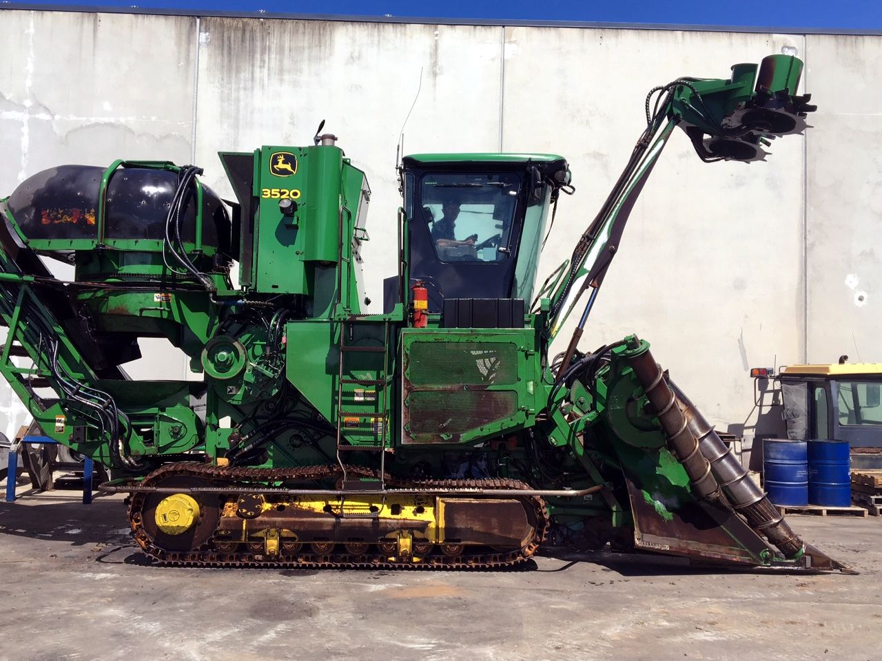
John Deere 3520 Track & Wheel Sugar Cane Harvester Diagnostic & Test Service Manual SN 120701- (TM114419) PDF - MJODTM114419.zip
John Deere Track & Wheel Sugar Cane Harvester 3520 Diagnostic & Testing Service Manual (TM114419)
TM114419 — Technical Manual for the John Deere Track & Wheel Sugar Cane Harvester 3520 (Diagnosis & Tests), supplied as a PDF.
Complete Diagnosis & Tests manual with Electrical Wiring Diagrams for John Deere 3520 (SN.120701-) Track & Wheel Sugar Cane Harvester, with all the shop information to maintain, diagnostic, repair, refurbish/rebuild like professional mechanics.
John Deere Track & Wheel Sugar Cane Harvester 3520 workshop Operation & Test manual includes:
* Numbered table of contents easy to use so that you can find the information you need fast.
* Detailed sub-steps expand on repair procedure information
* Numbered instructions guide you through every repair procedure step by step.
* Troubleshooting and electrical service procedures are combined with detailed wiring diagrams for ease of use.
* Notes, cautions and warnings throughout each chapter pinpoint critical information.
* Bold figure number help you quickly match illustrations with instructions.
* Detailed illustrations, drawings and photos guide you through every procedure.
* Enlarged inset helps you identify and examine parts in detail.
Total Pages: 4,776 pages
File Format: PDF (bookmarked, ToC, Searchable, Printable, high quality)
Language: English
MAIN SECTIONS
Foreword
Manual Identification-READ THIS FIRST!
Sugar Cane Flow
General Information
How to Use This Manual
Safety Information
Identification
Machine Specifications
Hydraulic Specifications
Recommended Tools for Diagnostics
Accessing Diagnostic Trouble Codes and Diagnostic Addresses
Recall, Record and Clear Diagnostic Trouble Codes
Diagnostic Information for Electrical Components
Diagnostic Information for Hydraulic Components
Standard Electrical Symbols
Standard Hydraulic Symbols
Maintaining Hydraulic Systems and Components
Basic Diagnostics
Standard Torque Chart Procedures
Intermittent Diagnostic Trouble Code (DTC) Diagnostics
Diagnostic Trouble Codes
Cab Primary Display Control Unit
Engine Control Unit
Power Train Propulsion Control Unit
Propulsion Steering Control Unit
Vehicle Control Unit
Improved Height Control Unit (IHU)
Observable Symptoms and System Diagnostics
Observable Symptoms
Engine
General Information
Calibrations or Operational and Preliminary Checks
Theory of Operation
Diagnostic Procedure
Fuel and Air Intake
General Information
Calibrations or Operational and Preliminary Checks
Theory of Operation
Schematic
Diagnostic Procedure
Electrical
General Information
Calibrations or Operational and Preliminary Checks
Theory of Operation
Schematic
Diagnostic Procedure
Control Units
General Reference
Calibrations or Operational and Preliminary Checks
Theory of Operation
Schematic
Diagnostic Procedure
Addresses for Cab Primary Display Control Unit
Addresses for Improved Height Control Unit
Addresses for Propulsion Steering Control Unit
Addresses for Power Train Propulsion Control Unit
Addresses for Vehicle Control Unit
Addresses for Virtual Terminal (in Cab)
Electrical Connector Information
General Information
X001-X099
X100-X199
X200-X299
X300-X399
X400-X499
X500-X599
Drive Train
Calibrations or Operational and Preliminary Checks
Theory of Operation
Schematic
Diagnostic Procedure
Steering and Brakes
General Information
Calibrations or Operational and Preliminary Checks
Service Brakes
Theory of Operation
Schematic
Diagnostic Procedure
Hydraulics
General Information
Calibrations or Operational and Preliminary Checks
Theory of Operation
Schematic
Diagnostic Procedure
Hydraulics Component Information
Accumulator
Cylinder, Actuator, or Piston
Check Valve
Filter
Valve Block, Assembly, or Gearcase
Cooler
Motor
Pump
Hydraulic Reservoir
Valve
Solenoid Valve
Operator Station
General
Air Suspension Seat and Armrest
Disassemble and Assemble
Schematic
Air Conditioning and Heating
Calibrations or Operational and Preliminary Checks
Theory of Operation
Schematic
Diagnostic Procedure
Special Tools
Special Tools and Part Numbers
tm114419 - 3520 Sugar Cane Harvester Track and Wheel Machines (S. N. 120701- )Diagnostic Technical Manual
Table of Contents
Foreword
Manual Identification—READ THIS FIRST!
Sugar Cane Flow
Section 210: General Information
Group 05A: How to Use This Manual
Information Available in Sections, Groups and Subgroups
Group 05B: Safety Information
Recognize Safety Information
Understand Signal Words
Follow Safety Instructions
Operation Safety
Service Precautions
Safety when Cleaning or Storing
Seat Safety Shut-Off
Prevent Machine Runaway
Handle Fluids Safely—Avoid Fires
Prevent Battery Explosions
Prepare for Emergencies
Battery Safety
Jumping the Battery
Precautions for Alternators
Handling Batteries Safely
Charging the Batteries
Avoid High-Pressure Fluids
Escaping High Pressure Fluid Can Cause Serious Injury
Park Machine Safely
Avoid Power Lines
Support Machine Properly
Wear Protective Clothing
Work in Clean Area
Service Machines Safely
Work In Ventilated Area
Illuminate Work Area Safely
Replace Safety Signs
Use Proper Lifting Equipment
Use Handles and Steps
Use Cylinder Safety Stops
Remove Paint Before Welding or Heating
Avoid Heating Near Pressurized Fluid Lines
Avoid Explosive Release of Pressurized Coolants
Service Accumulator Safely
Service Tires Safely
Practice Safe Maintenance
Use Proper Tools
Decommissioning — Proper Recycling and Disposal of Fluids and Components
Live With Safety
Operate Safely
Avoid Tip-Overs
Keep Riders Off Machine
Stored Fuel Can Be Dangerous
Handle Fuel Safely—Avoid Fires
Avoid Fires
Handle Starting Fluid Safely
Handle Chemical Products Safely
Avoid Contact with Moving Parts
Keep Hands Away from Knives
Tilt Cab
Avoid Backover Accidents
Transport Machine Safely
Use Safety Lights and Devices
Group 05C: Identification
Identification Numbers
Machine Serial Number
Engine Serial Number
Interpreting the Serial Number of Your Machine 13 digits PIN
Interpreting the Serial Number of Your Machine 17 digits PIN
Group 05D: Machine Specifications
Machine Specifications
Group 05E: Hydraulic Specifications
Hydraulic Specifications
Group 05F: Recommended Tools for Diagnostics
Recommended Tools
Group 05G: Accessing Diagnostic Trouble Codes and Diagnostic Addresses
Accessing Diagnostic Trouble Codes and Addresses
Accessing Technician Mode
Quick Procedure - Access Diagnostic Trouble Codes
Quick Procedure - Access Diagnostic Addresses
Group 05H: Recall, Record and Clear Diagnostic Trouble Codes
Recall, Record, and Clear Diagnostic Trouble Codes
Group 05I: Diagnostic Information for Electrical Components
Electrical Designators
Visually Inspect Electrical System
Wire Harness Test
Alternator Test
Group 05J: Diagnostic Information for Hydraulic Components
Hydraulic Designators
Troubleshooting Tips
Visually Inspect Hydraulic System
Group 05K: Standard Electrical Symbols
Electrical Symbols
Group 05L: Standard Hydraulic Symbols
Standard Hydraulic Symbols
Group 05M: Maintaining Hydraulic Systems and Components
Aeration and Cavitation
Hydraulic Components
Oil Storage and Filling
Oil Filtration
Group 05N: Basic Diagnostics
Seven Basic Steps
Troubleshooting Unresolved Problems
Group 05O: Standard Torque Chart Procedures
Unified Inch Bolt and Screw Torque Values
Metric Bolt and Screw Torque Values
Group 05: Intermittent Diagnostic Trouble Code (DTC) Diagnostics
Intermittent Diagnostic Trouble Code (DTC) Diagnostics
Section 211: Diagnostic Trouble Codes
Group 10A: Cab Primary Display Control Unit
PDU 000628.02 - Program Memory Fault
PDU 000628.12 - Program Memory Fault
PDU 000629.12 - PDU Control Unit Fault
PDU 000639.12 - PDU CAN Error Limit Exceeded
PDU 000639.14 - PDU CAN Error Limit Exceeded
PDU 002000.09 - ECU Message Missing
PDU 002003.09 - PTI or PTP Message Missing
PDU 002019.09 - SSU Message Missing
PDU 002038.09 - SDU Message Missing
PDU 002039.09 - Source Address 039 Message Missing
Group 10B: Engine Control Unit
ECU 000091.09 - CAN Throttle Message Error
ECU 000094.03 - Lo Pressure Fuel Pressure Signal Out of Range HI
ECU 000094.04 - Lo Pressure Fuel Signal Out of Range Lo
ECU 000094.17 - Lo Pressure Fuel Signal Slightly Lo
ECU 000097.03 - Water-in-Fuel Signal Out of Range HI
ECU 000097.04 - Water-in-Fuel Signal Out of Range Lo
ECU 000097.16 - Water-in-Fuel Detected
ECU 000100.01 - Engine Oil Pressure Signal Extremely Lo
ECU 000100.04 - Engine Oil Pressure Signal Out of Range Lo
ECU 000100.18 - Engine Oil Pressure Signal Moderately Lo
ECU 000100.31 - Oil Pressure is not Zero with Engine Stopped
ECU 000102.02 - Intake Manifold Pressure Signal Invalid
ECU 000102.03 - Intake Manifold Pressure Signal Out of Range HI
ECU 000102.04 - Intake Manifold Pressure Signal Out of Range Lo
ECU 000103.00 - Turbo Speed Signal Extremely HI
ECU 000103.05 - Turbo Speed Sensor Circuit has HI Resistance
ECU 000103.08 - Turbo Speed Signal Incorrect
ECU 000103.31 - Turbo Speed Signal Missing
ECU 000105.00 - Intake Manifold Air Temperature Signal Extremely HI
ECU 000105.03 - Intake Manifold Air Temperature Signal Out of Range HI
ECU 000105.04 - Intake Manifold Air Temperature Signal Out of Range Lo
ECU 000105.15 - Intake Manifold Air Temperature Signal Slightly HI
ECU 000105.16 - Intake Manifold Air Temperature Signal Moderately HI
ECU 000107.00 - Air Filter Pressure Differential Extremely HI
ECU 000108.02 - Barometric Pressure Signal Invalid
ECU 000110.00 - Engine Coolant Temperature Signal Extremely HI
ECU 000110.03 - Engine Coolant Temperature Signal Out of Range HI
ECU 000110.04 - Engine Coolant Temperature Signal Out of Range Lo
ECU 000110.15 - Engine Coolant Temperature Signal Slightly HI
ECU 000110.16 - Engine Coolant Temperature Signal Moderately HI
ECU 000110.17 - Engine Coolant Temperature Signal Slightly Lo
ECU 000157.03 - Fuel Rail Pressure Signal Out of Range HI
ECU 000157.04 - Fuel Rail Pressure Signal Out of Range Lo
ECU 000157.10 - Fuel Rail Pressure Rate of Change Abnormal
ECU 000157.17 - Fuel Rail Pressure Not Developed
ECU 000158.17 - ECU Power Down Error
ECU 000174.00 - Fuel Temperature Signal Extremely HI
ECU 000174.03 - Fuel Temperature Signal Out of Range HI
ECU 000174.04 - Fuel Temperature Signal Out of Range Lo
ECU 000174.16 - Fuel Temperature Signal Moderately HI
ECU 000189.00 - Engine Speed Derate Condition
ECU 000189.09 - Engine Speed Derate Condition
ECU 000190.00 - Engine Speed Extremely HI
ECU 000412.00 - EGR Temperature Signal Extremely HI
ECU 000412.03 - EGR Temperature Signal Out of Range HI
ECU 000412.04 - EGR Temperature Signal Out of Range Lo
ECU 000412.15 - EGR Temperature Signal Slightly HI
ECU 000412.16 - EGR Temperature Signal Moderately HI
ECU 000441.03 - Gear Oil Temperature Signal Out of Range HI
ECU 000441.04 - Gear Oil Temperature Signal Out of Range Lo
ECU 000611.03 - Injector Shorted
ECU 000611.04 - Injector Shorted
ECU 000627.01 - All Electronic Injector Circuits Have HI Resistance
ECU 000627.18 - Injector Power Supply Voltage Moderately Low
ECU 000629.12 - ECU EEPROM
ECU 000629.13 - ECU Boot Block