
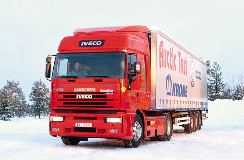
Iveco EuroTech EuroStar Cursor Trucks Workshop Repair Service Manual 1992-2002 PDF - MIVCETES9202OPES.zip
An all-inclusive service and repair guide featuring complete electrical wiring diagrams for the Iveco EuroTech and EuroStar truck lines, packed with the technical data needed to service, troubleshoot, fix, and overhaul these vehicles the way professional technicians do.
The workshop service and repair manual for Iveco EuroTech and EuroStar trucks contains:
* Numbered table of contents easy to use so that you can find the information you need fast.
* Detailed sub-steps expand on repair procedure information
* Numbered instructions guide you through every repair procedure step by step.
* Troubleshooting and electrical service procedures are combined with detailed wiring diagrams for ease of use.
* Notes, cautions and warnings throughout each chapter pinpoint critical information.
* Bold figure number help you quickly match illustrations with instructions.
* Detailed illustrations, drawings and photos guide you through every procedure.
* Enlarged inset helps you identify and examine parts in detail.
603.43.391 - Iveco Trucks EuroTech Cursor, EuroStar Cursor Repair Manual ('92-'02).pdf
603.93.121 - Iveco Trucks EuroTrakker, EuroTech, EuroStar Cursor 8-10-13 Electrical Wiring Diagrams.pdf
PRODUCT DETAILS:
Total Pages: 1,321 pages
File Format: PDF (bookmarked, ToC, Searchable, Printable, high quality)
Language: English
MAIN SECTIONS
General 1
Engine 2
Clutch 3
Transmission* 4
Intarder - ZF hydraulic retarder 5
Propeller shafts 6
Rear axles 7
Axles 8
Suspension 9
Wheels and tyres 10
Steering system 11
Hydraulic system - Brakes 12
Scheduled Maintenance 13
TABLE OF CONTENTS
EUROTECH CURSOR - EUROSTAR CURSOR...1
REPAIR MANUAL...1
NOTE...3
Graphs and symbols...4
INDEX...5
SECTION 1 - General...6
General...6
COMPOSITION OF MODELS...8
P.I.C. CODE NUMBER...12
Vehicle Identification Data (EUROTECH)...16
Vehicle Identification Data (EUROSTAR)...17
FILLING UP...18
International designations of lubricants and fluids...19
SECTION 2 - Engine...20
Engine...20
VIEWS OF THE ENGINE...26
TECHNICAL DESIGNATION...28
GENERAL CHARACTERISTICS...31
ASSEMBLY CLEARANCE DATA...34
FAULT DIAGNOSIS...40
DESCRIPTION...40
DIAGNOSTIC INSTRUMENTS...40
CONTROL UNIT TEST...41
ENGINE TEST...41
AUXILIARY FUNCTIONS...41
DETECTION OF MECHANICAL FAILURE...42
TIGHTENING TORQUE...45
TOOLS...50
ENGINE REMOVAL - REFITTING...60
Removal...60
Refitting...61
DISMANTLING THE ENGINE ON THE BENCH...64
REPAIR OPERATIONS...71
CYLINDER BLOCK...71
Checks and measurements...71
CYLINDER LINERS...72
Replacing cylinder liners...73
Removal...73
Fitting and checking protrusion...73
CRANKSHAFT...74
Measuring main journals and crank pins...75
Preliminary measurement of main and big end bearing shell selection data...76
Replacing the timing control gear and oil pump...84
Checking main journal installation clearance...84
Checking crankshaft end float...85
PISTON-CONNECTING ROD ASSEMBLY...86
Removal...86
Measuring the diameter of the pistons...87
Conditions for correct gudgeon pin-piston coupling...87
Piston rings...88
CONNECTING ROD...89
Bushings...90
Checking connecting rods...90
Mounting the piston rings piston assembly...91
Mounting the piston rings...91
Fitting the big end bearing shells...91
Fitting connecting rod - piston assemblies in the cylinder liners ...92
Checking piston protrusion...92
Checking assembly clearance of big end pins...94
CYLINDER HEAD...94
Taking down the valves...94
Checking the planarity of the head on the cylinder block...94
VALVES...94
Removing deposits and checking the valves...94
VALVE GUIDES...95
Replacing of valve guides...96
Replacing - Reaming the valve seats...96
REPLACING INJECTOR HOLDER CASES...96
Removal...96
Checking protrusion of injectors...98
TIMING GEAR...99
Checking cam lift and pin alignment...99
Camshaft...100
Bushes...100
Replacing camshaft bushes using beater 99360499...101
Valve springs...102
Fitting the valves and oil seal ring...102
ROCKER SHAFT...103
ROCKERS...103
LUBRICATION...104
Oil pump...106
Overpressure valve...106
Oil pressure control valve...107
Heat exchanger...107
Engine oil filters...108
COOLING...109
Water pump...109
Thermostat...109
TURBOCHARGING...112
Turbocharger...112
Holset HX55V turbocharger...114
ACTUATOR ADJUSTMENT...117
VGT Control solenoid valve...117
Holset HY55V turbocharger...118
Actuator...119
Solenoid valve for VGT control...119
FEEDING...120
Fuel pump...121
Injector-pump...121
Pumping element...121
Nozzle...121
Solenoid valve...121
Replacing injectors-pump...121
INJECTOR PHASES...122
Filling phase...122
Injection phase...123
Pressure Reduction phase...123
ASSEMBLING THE ENGINE ON THE BENCH...124
DIAGRAM SHOWING THE UNDERBLOCK FIXING SCREWS TIGHTENING ORDER...126
Fitting the connecting rod-piston assembly into the cylinder liners...127
ENGINE FLYWHEEL...130
Fitting engine flywheel...130
Fitting camshaft...131
Fitting pump-injectors...132
Fitting rocker-arm shaft assembly...132
Camshaft timing...133
Phonic wheel timing...135
Adjusting rocker armclearance, intake, exhaust and pre-load of pump injector governing rocker arms...136
ENGINE COMPLETION...138
SECTION 3 - Clutch...140
Clutch...140
DESCRIPTION...142
Clutch...142
CHARACTERISTICS AND DATA...142
DIAGNOSTICS...143
TIGHTENING TORQUES...146
TOOLS...146
REMOVING AND REFITTING...147
Removal...147
Refitting...147
REMOVING AND FITTING BACK THE THRUST BEARING ...147
REPLACING THE SUPPORT BEARING OF THE CLUTCH SHAFT...147
DRIVEN PLATE CONTROL...148
Damping hub control...148
Friction seal...148
BLEEDING AIR FROM THE CLUTCH SYSTEM...148
HYDRAULIC CONTROL...149
CLUTCH ACTUATOR FOR ZF 16 S151/181/221 GEARBOX...150
Fitting and adjusting the clutch wear indicator...150
Push rod adjustment (new clutch)...151
CLUTCH ACTUATOR FOR EUROTRONIC GEARBOX...152
Clutch actuator push rod adjustment (new clutch)...152
Fitting the clutch actuator...152
Replacing the clutch actuator...152
CHECKING AND ADJUSTING THE CLUTCH PEDAL STOPS (excluded vehicles with EuroTronic gearbox)...153
Clutch stop...153
Clutch pedal idle stroke...153
Pedal timing gear stroke...153
SECTION 4 - Gearbox...154
Gearbox...154
Gearboxes: ZF 16 S 181 D.D. ZF 16 S 181 O.D. ZF 16 S 221 D.D...157
LOCATION OF GEARBOX DESCRIPTION PLATE...159
DESCRIPTION...160
OPERATION...162
Slow range...162
Fast range...163
EPICYCLIC REDUCTION GEAR CONTROL...164
Reduced speeds...164
Normal speeds...165
SPECIFICATIONS AND DATA...166
TIGHTENING TORQUES...170
TOOLS...171
GEARBOX FAULT DIAGNOSIS...176
REMOVING-REFITTING THE GEARBOX...179
Removal...179
Refitting...180
OVERHAULING THE GEARBOX...181
Servoshift gear box...181
Removal...181
Refitting...181
Disassembly...181
Assembly...183
Removing the rear box...186
Removing the epicyclic reduction gear unit (ERG)...186
Fitting the epicyclic reduction gear unit (ERG)...189
Refitting the epicyclic reduction gear unit (ERG) rear box ...192
Removing the gearbox...192
Removing the main shaft...195
Removing the drive input shaft...198
Removing the transmission shaft...199
CHECKS...199
Gearbox...199
Hubs - sliding sleeves - forks...199
Bearings...199
Shafts - gears...199
Synchronizing devices...199
BK-type single-cone synchronizing devices...199
Fitting the transmission shaft...200
Fitting the drive input shaft...200
Fitting the main shaft...201
Adjusting the main shaft...203
Fitting the gearbox...204
Oil pump...205
Adjusting the transmission shaft bearing end float...205
Drive input shaft cover...206
PNEUMATIC CONTROL OF GEARBOX...208
ZF gearboxes with INTARDER hydraulic retarder, types: 16 S 151 D.D. 16 S 181 D.D. 16 S 221 D.D...210
SPECIFICATIONS AND DATA...212
TOOLS...213
Removing the hydraulic retarder from the gearbox on the stand...220
Refitting the hydraulic retarder...220
Removing the epicyclic reduction gear unit (ERG) rear box...221
Removing the epicyclic reduction gear unit (ERG)...221
Component parts of the epicyclic reduction gear unit...224
Fitting the epicyclic reduction gear unit (ERG)...225
Refitting the epicyclic reduction gear unit (ERG) rear box...227
Gearbox EUROTRONIC 1800...229
DESCRIPTION...231
CHARACTERISTICS AND DATA...233
TIGHTENING TORQUES...236
EQUIPMENT...237
DIAGNOSIS OF MECHANICAL TYPE FAULTS...243
EUROTRONIC 1800 TRANSMISSION REMOVAL-REFITTING...246
Removal...246
Refitting...247
REPAIRS...248
Disassembly of front box...248
Disassembling the intermediate casing...249
Disassembly of rear box and epicyclic reduction unit...251
Installation of rear box and epicyclic reduction unit...253
Axial clearance regulation on epicyclic reduction gear bearing...253
Removal of primary shaft...257
Primary shaft installation...258
Removal of Splitter synchroniser...260
Installation of Splitter synchroniser...260
Forks installation-disinstallation...260
Secondary shafts...260
Central box installation...261
Shafts timing...263
Disinstallation of movement input shaft...264
Installation of movement input shaft...265
Installation of front box...265
Disinstallation of front cover...266
Installation of front cover...266
Regulation of axial clearance on movement input shaft bearing ...267
Regulation of axial clearance on secondary shaft bearings...267
EUROTRONIC IT (INTARDER)...271
CHARACTERISTICS AND DATA...271
REPAIRS...272
Disinstallation of rear box...272
Rear box installation...273
Regulation of axial clearance on epicyclic reduction gear bearing...273
Regulation of axial clearance on stator...274
CLUTCH ACTUATOR...275
Description...275
CHARACTERISTICS AND DATA...275
SAFETY RULES...276
Disinstallation...277
Installation...279
Operating checks...280
Measure of piston stroke...280
Gearbox EuroTronic 12 AS 2301 D.D...282
DESCRIPTION...284
SPECIFICATIONS AND DATA...285
TIGHTENING TORQUES...288
TOOLS...289
OVERHAULING THE GEARBOX ...294
Checks...294
Gearbox actuator...294
Removal...294
Refitting...295
Removing the rear box...295
Removing the rear box...296
Removing the epicyclic reduction gear train (E.R.G.)...297
Fitting the epicyclic reduction gear train (E.R.G.)...299
Adjusting epicyclic reduction gear train bearing end float...300
Adjusting main shaft end float...301
Synchronizing device assembly for engaging normal or reduced gears...303
Removal...303