

You pull a resistor from a circuit board. There is no printed value—just a series of colored bands.
Can you determine its resistance without reaching for a meter?
For electronics technicians, students, and hobbyists, resistor color codes are worth understanding even when a digital multimeter is sitting nearby. The bands can tell you what value the resistor was intended to be, while your meter tells you what resistance you are actually measuring.
That distinction can become extremely useful during troubleshooting.
Why do resistors use color bands?
Many through-hole resistors are too small for easily readable printed values. Manufacturers therefore encode resistance and tolerance using standardized colored bands.
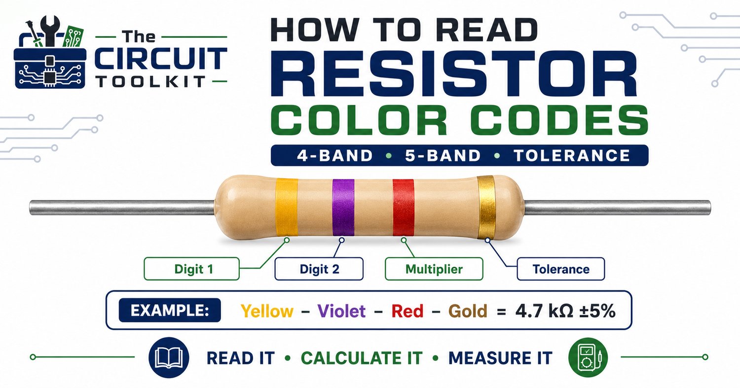
A typical 4-band resistor uses:
Band 1: First digit
Band 2: Second digit
Band 3: Multiplier
Band 4: Tolerance
A 5-band resistor adds another significant digit:
Band 1: First digit
Band 2: Second digit
Band 3: Third digit
Band 4: Multiplier
Band 5: Tolerance
The key is recognizing which end to start from.
Finding the first band
The tolerance band is normally separated slightly from the other bands and is often gold or silver on 4-band resistors. Orienting that band toward the right gives you the normal reading direction.
On some modern precision resistors, particularly 5-band devices, orientation can be less obvious. If there is uncertainty, don't guess. Compare the markings with documentation or verify the resistance electrically.
Remember the color sequence
For significant digits, the basic sequence is:
Black 0 — Brown 1 — Red 2 — Orange 3 — Yellow 4 — Green 5 — Blue 6 — Violet 7 — Gray 8 — White 9
The multiplier determines how many times the significant-digit value is multiplied by ten.
For example, consider a 4-band resistor:
Yellow – Violet – Red – Gold
Yellow = 4
Violet = 7
Red multiplier = ×100
Therefore:
47 × 100 = 4,700 Ω
or:
4.7 kΩ
Gold indicates ±5% tolerance.
So, the nominal value is 4.7 kΩ ±5%.
What does tolerance actually mean?
Tolerance specifies the acceptable manufacturing range around the nominal resistance.
For our 4.7 kΩ ±5% example:
5% of 4,700 Ω = 235 Ω.
The resistor could therefore be within specification from approximately:
4,465 Ω to 4,935 Ω
A meter reading of 4.68 kΩ would be completely normal.
A reading of 2.1 kΩ would require further investigation.
Reading a 5-band resistor
Five-band resistors commonly appear where tighter tolerance or more precise values are required.
Suppose the colors are:
Brown – Black – Black – Red – Brown
The first three bands give:
1 – 0 – 0 = 100
Red gives a multiplier of ×100:
100 × 100 = 10,000 Ω
So the resistor is:
10 kΩ
The final brown tolerance band indicates ±1%.
The method is almost identical to a 4-band resistor; you simply have one additional significant digit.
Why technicians should still use a multimeter
Color codes tell you the resistor's nominal value. They do not prove the resistor is healthy.
Resistors can change value because of overheating, electrical overstress, environmental damage, or physical deterioration.
During troubleshooting, compare the color-code value with the measured value.
But remember: in-circuit resistance measurements can be misleading.
Other components may create parallel paths around the resistor, causing the meter to display a lower resistance than the resistor actually has.
If the reading doesn't make sense, de-energize the circuit, safely discharge stored energy, and isolate one end of the resistor when appropriate.
Look for evidence of overheating
A resistor that has experienced excessive power dissipation may show:
- Discoloration
- Cracking
- Darkened PCB material
- Damaged coating
- Changed resistance
- Completely open resistance
Don't simply replace a burned resistor and apply power again.
Ask why it overheated.
The real fault may be downstream: a shorted semiconductor, failed capacitor, incorrect supply voltage, or another condition forcing excessive current through the resistor.
Use resistance and power together
Resistance is only part of resistor selection.
Power matters too.
The basic relationship is:
P = I²R
or:
P = V²/R
A circuit can contain a resistor with exactly the correct resistance value and still fail if its power rating is inadequate.
This is particularly important in power supplies, LED circuits, transistor bias networks, current-sensing circuits, and voltage-dropping applications.
A better troubleshooting habit
When you encounter a suspicious resistor:
Read it. Calculate it. Measure it. Understand why it failed.
That sequence turns resistor identification into actual circuit troubleshooting.
Learning the color code also makes schematics, breadboards, prototypes, and repair work faster because you begin recognizing common values almost instantly.
For a bench-side reference, your current Circuit Toolkit lineup includes the Resistor Color Code Guide — One-Page Bench Reference with Full Table & Examples, designed specifically to keep the complete code and practical examples within reach at the workbench.
Browse The Circuit Toolkit reference guides
Safety: Resistance measurements should normally be performed with equipment de-energized and stored energy safely discharged. Never place a meter configured for resistance measurement across an energized circuit.