

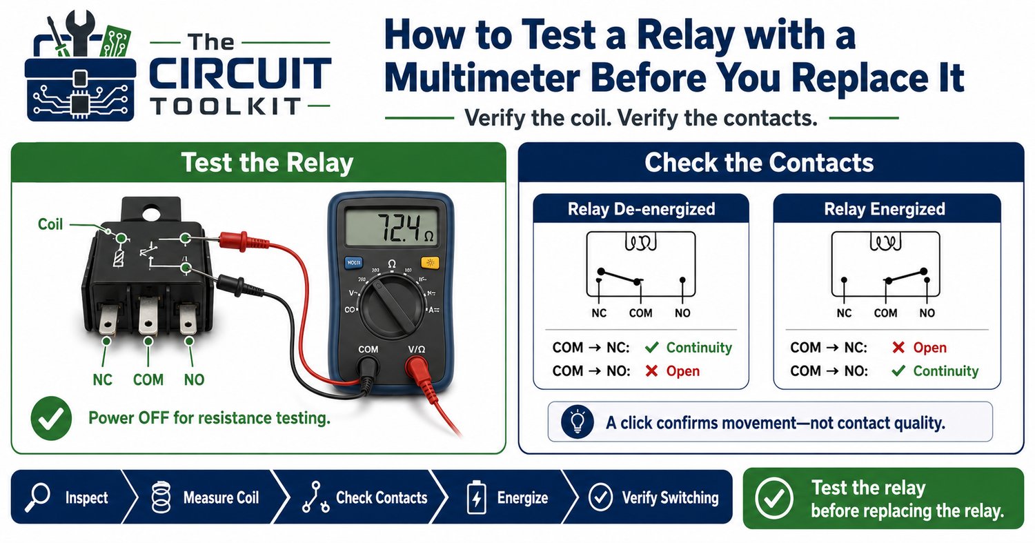
Relays are found in everything from industrial control panels and automotive systems to power supplies and embedded electronics. Because they switch electrical loads, they're often blamed when equipment stops working.
But replacing a relay simply because "it clicks" or "doesn't click" can waste both time and money.
A relay has two main parts:
- The coil, which creates a magnetic field.
- The contacts, which open or close the electrical circuit.
A proper relay test verifies both sections. Fortunately, a digital multimeter can perform most of the checks you need before deciding whether the relay has actually failed.
Understand What You're Testing
Most electromechanical relays contain:
- Two coil terminals
- One Common (COM) terminal
- One Normally Open (NO) contact
- One Normally Closed (NC) contact
When the coil is not energized:
- COM and NC are connected.
- COM and NO are open.
When the coil is energized:
- COM and NC open.
- COM and NO close.
Understanding this sequence makes every measurement meaningful.
Step 1: Inspect the Relay
Before making electrical measurements, perform a visual inspection.
Look for:
- Burn marks
- Melted housing
- Loose terminals
- Corrosion
- Cracked case
- Evidence of overheating
Physical damage alone may explain the failure.
Step 2: Measure the Coil Resistance
Disconnect power from the circuit before testing.
Set your multimeter to resistance (Ω).
Measure across the relay coil terminals.
A healthy relay coil should measure a finite resistance.
Typical values vary by relay design, so compare your reading with the manufacturer's datasheet or a known-good relay whenever possible.
If the meter reads:
- OL (open circuit): The coil is likely open.
- Near 0 Ω: The coil may be internally shorted.
Either condition usually indicates a failed relay.
Step 3: Check the Contact State
With the relay de-energized, use continuity mode.
Measure:
- COM to NC
- COM to NO
Normally you should find:
- COM → NC: Continuity
- COM → NO: Open circuit
If both contacts appear open—or both appear shorted—the relay may have failed mechanically or the contacts may have welded together.
Step 4: Energize the Coil
If it is safe to do so, apply the relay's rated coil voltage using an appropriate power source.
You should hear a distinct click as the armature moves.
Now repeat the continuity measurements.
A properly operating relay should now show:
- COM → NC: Open
- COM → NO: Continuity
The contacts should reverse exactly as expected.
Step 5: Don't Trust the Click Alone
One of the biggest troubleshooting mistakes is assuming that a clicking relay is automatically good.
A relay can click while still having:
- Burned contacts
- High contact resistance
- Welded contacts
- Mechanical damage
The click only confirms that the coil is moving the mechanism.
It does not confirm the contacts are carrying current correctly.
High-Resistance Contacts
Some relay failures are difficult to detect with continuity testing alone.
The contacts may still close but develop excessive resistance because of wear, contamination, or arcing.
In high-current applications, this resistance creates unwanted voltage drop and heat.
When troubleshooting an energized circuit, a voltage drop test across the relay contacts can reveal problems that continuity testing cannot.
Common Mistakes
Avoid these common errors:
- Measuring resistance on an energized relay.
- Assuming every relay has the same terminal arrangement.
- Ignoring the relay datasheet.
- Replacing a relay before verifying the control voltage reaches the coil.
- Forgetting to inspect the socket and connector pins.
Sometimes the relay isn't the problem—the control circuit never energizes it.
Safety First
Before testing:
- Disconnect power whenever measuring resistance or continuity.
- Verify the relay's coil voltage before energizing it.
- Use insulated probes.
- Never bypass safety interlocks to force relay operation.
- Keep clear of high-voltage circuits while troubleshooting.
A methodical process is both safer and more accurate.
Conclusion
Testing a relay takes only a few minutes, but it can prevent unnecessary replacement of perfectly good components.
Verify the coil.
Verify the contacts.
Confirm the switching action.
And remember: a clicking relay is only one piece of evidence. Good troubleshooting always confirms electrical performance—not just mechanical movement.
If you're building your troubleshooting skills, the Digital Multimeter Quick Reference Guide and the Beginner Circuit Troubleshooting Guide available from The Circuit Toolkit provide practical workflows for testing relays, switches, sensors, and other electrical components with confidence. These products complement today's topic and align with your current troubleshooting-focused product lineup.