

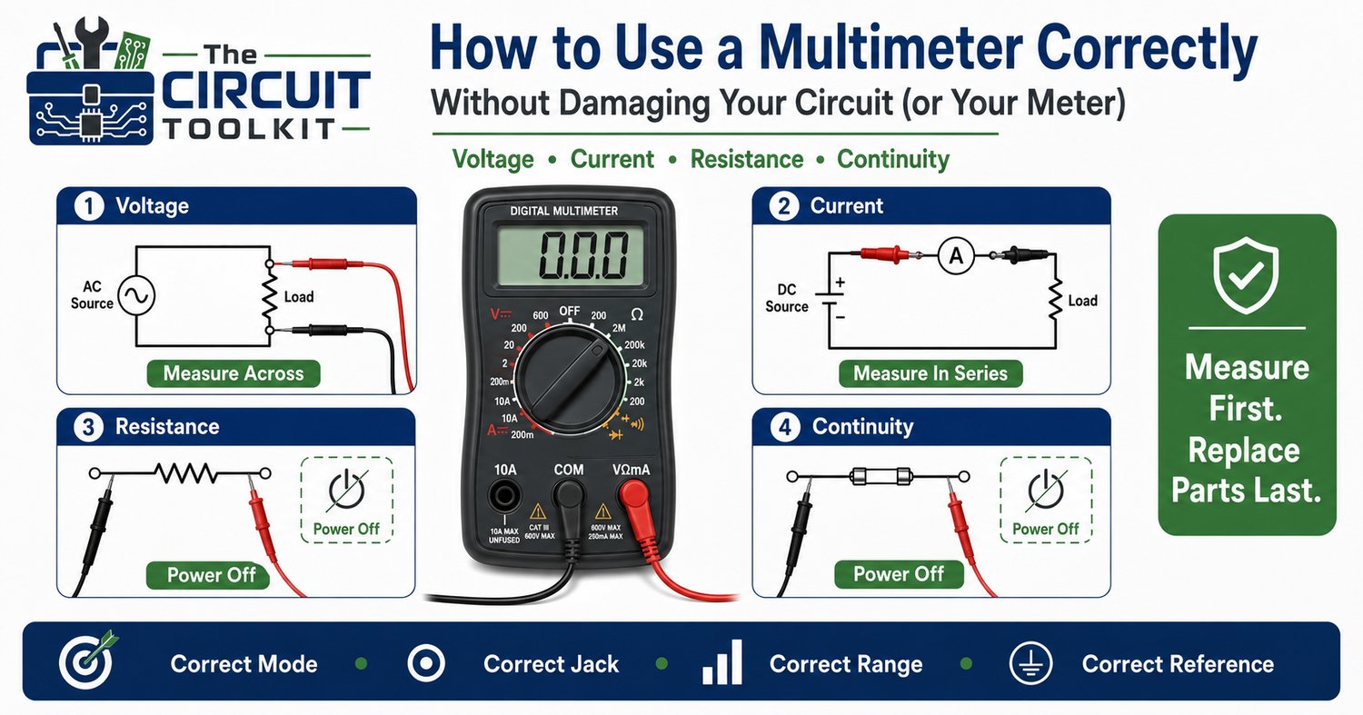
If there's one tool every electronics technician owns, it's the digital multimeter (DMM).
Whether you're troubleshooting a power supply, checking a resistor, verifying a fuse, or diagnosing a dead circuit board, the multimeter is usually the first instrument you'll reach for.
Unfortunately, it's also one of the most commonly misused tools.
A single incorrect setting can blow the meter's fuse, damage the meter, or produce misleading measurements that send you troubleshooting in the wrong direction.
Learning to use a multimeter correctly isn't just about protecting the instrument—it's about collecting accurate information that leads you to the real fault.
The Four Measurements You'll Use Most
Most troubleshooting revolves around four basic measurements:
- Voltage
- Resistance
- Continuity
- Current
Each requires a different meter configuration.
Knowing when and how to use each one is far more important than memorizing button locations.
Measuring Voltage
Voltage measurements are made across two points in a circuit.
The circuit remains energized during the measurement when appropriate and safe.
For example, to verify a 12 V power supply:
- Set the meter to DC volts.
- Connect the black lead to the circuit reference (ground or return).
- Touch the red lead to the point you want to measure.
The meter displays the voltage difference between those two points.
If you're troubleshooting, don't stop at the power supply.
Measure:
- At the connector
- At the load
- Across switches
- Across suspected high-resistance connections
Comparing these readings often reveals where voltage is being lost.
Measuring Resistance
Resistance measurements are completely different.
The meter applies a small internal test current.
Because of this:
The circuit should normally be de-energized and stored energy safely discharged before measuring resistance.
Measuring resistance on a powered circuit can produce inaccurate readings and may damage the meter.
Also remember:
Components connected in parallel can affect the reading.
If a resistor appears lower than expected, another current path may exist.
Continuity Testing
Continuity mode is simply a quick resistance check with an audible beep.
It's useful for checking:
- Wires
- PCB traces
- Fuses
- Switches
- Connectors
But remember:
Continuity only confirms that a path exists.
It does not prove that the path can carry normal operating current without excessive voltage drop.
That's why continuity testing and voltage-drop testing complement each other.
Measuring Current
Current measurements require the greatest care.
Unlike voltage measurements, the meter must become part of the circuit.
Current is measured in series with the load.
One of the most common beginner mistakes is placing the meter, configured for current, directly across a voltage source.
Doing so effectively creates a low-resistance path through the meter and may immediately blow the meter's current fuse or damage the instrument.
Before measuring current:
- Verify the meter is in the correct input jack.
- Select the correct current range.
- Confirm you're inserting the meter in series, not in parallel.
Three Common Mistakes
1. Measuring resistance on a live circuit
This can produce false readings and may damage the meter.
Always remove power before resistance or continuity testing.
2. Using the wrong input jack
Many meters have separate inputs for current measurements.
Always verify the lead locations before making a measurement.
A surprising number of blown meter fuses happen simply because the red lead was left in the current input after the previous test.
3. Measuring the wrong reference point
Voltage measurements are only meaningful relative to the correct reference.
If your ground reference changes, your voltage readings change too.
Always identify the proper return point before diagnosing the circuit.
Build a Better Troubleshooting Habit
Professional technicians rarely take a single measurement.
Instead they compare measurements.
Ask yourself:
- What voltage should be here?
- Does the supply reach this point?
- What changed compared to the previous node?
- Is the voltage drop expected?
- Does the resistance match the schematic?
- Is the current reasonable?
Every measurement should answer a question.
A Simple Checklist
Before touching the probes to the circuit:
✓ Correct measurement mode
✓ Correct input jack
✓ Correct range
✓ Correct reference point
✓ Circuit energized or de-energized as appropriate
✓ Understand what you're expecting to measure
That 15-second check can prevent expensive mistakes.
Conclusion
A multimeter doesn't diagnose circuits.
It provides measurements.
Your understanding of those measurements is what solves the problem.
When used correctly, a DMM becomes the fastest path from symptom to root cause.
If you're building your troubleshooting skills, the Beginner Circuit Troubleshooting Guide PDF | Step-by-Step Electronics Repair Checklist in The Circuit Toolkit provides a structured workflow for deciding what to measure, where to measure it, and how to interpret the results. It complements the techniques discussed here and helps build consistent diagnostic habits
Safety Reminder
Voltage measurements should only be performed using appropriately rated test equipment and safe work practices. Resistance and continuity measurements should normally be performed only after the circuit has been de-energized and stored energy has been safely discharged. Follow the equipment manufacturer's procedures and applicable electrical safety requirements.