

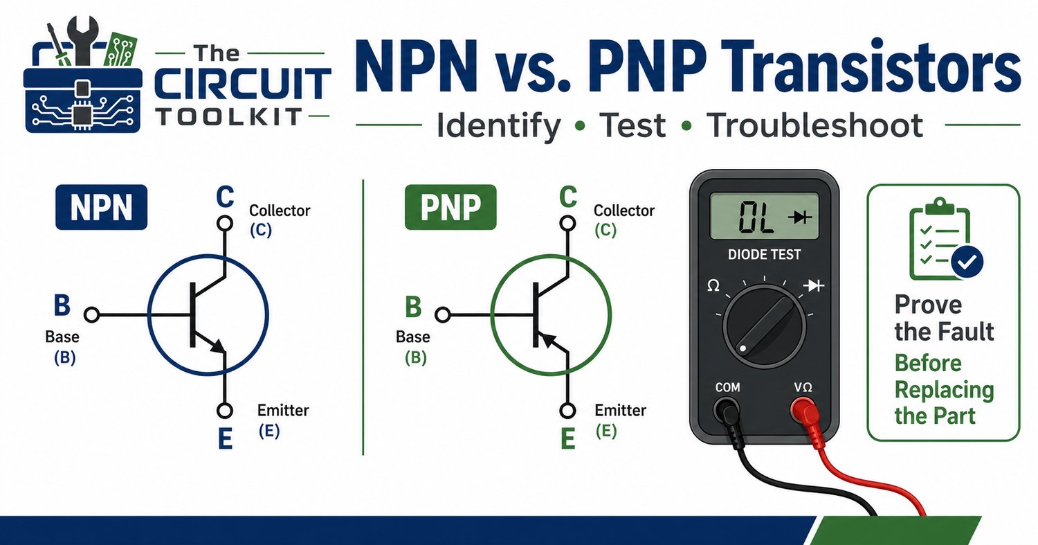
Transistors are everywhere. They switch relays, control LEDs, amplify signals, drive motors, interface microcontrollers with larger loads, and perform countless other jobs.
When a transistor circuit fails, however, replacing the transistor immediately is rarely the best first move. A better technician asks three questions:
What type of transistor is it? What should its junctions measure? And what is the surrounding circuit telling it to do?
For bipolar junction transistors, or BJTs, answering those questions starts with understanding NPN and PNP devices.
Three terminals, two junctions
A BJT has three terminals:
Base (B): the control terminal.
Collector (C): one side of the primary current path.
Emitter (E): the other side of that path.
An NPN transistor is commonly used as a low-side switch. When sufficient base-emitter voltage and base current are provided, the transistor can conduct collector current toward the emitter.
A PNP transistor works with opposite polarities and is commonly encountered in high-side switching arrangements.
That does not mean you can identify a transistor's physical pins just by knowing it is NPN or PNP. Pinouts vary by device and package.
Always verify the datasheet before assuming which lead is base, collector, or emitter.
Think of a BJT as two PN junctions
A useful troubleshooting model is to consider the transistor's base-emitter and base-collector junctions individually.
With the circuit de-energized and stored energy safely discharged, a digital multimeter's diode-test mode can help evaluate these junctions.
For a typical healthy NPN silicon BJT, placing the red meter lead on the base and the black lead on either the emitter or collector will normally produce a forward-junction reading, often roughly 0.6–0.7 V. Reversing the probes should normally indicate an open junction.
For a PNP device, the probe polarity is reversed: the black lead goes to the base for the corresponding forward-junction tests.
These are diagnostic guidelines, not universal pass/fail numbers. Device construction, temperature, Darlington configurations, and surrounding circuitry can change the reading.
What does a failed transistor look like?
A shorted transistor may show very low readings between terminals in both probe directions.
An open junction may produce an open indication in both directions where a normal forward junction should exist.
But there is another important possibility:
The transistor may be perfectly healthy.
A BJT that isn't switching can be caused by a failed base resistor, missing control signal, damaged PCB trace, incorrect supply voltage, open load, or bad ground connection.
That is why troubleshooting the circuit is more valuable than simply testing the component.
Check the transistor while the circuit operates
When powered, measurements can be performed safely; examine what the transistor is actually being commanded to do.
For an NPN silicon transistor used as a switch, measure the base voltage relative to its emitter.
If the control circuit is supposed to turn the transistor on but there is essentially no base-emitter drive, replacing the transistor probably won't fix the problem. Trace the control path backward.
If adequate base drive exists but the expected collector current or collector voltage change doesn't occur, investigate the transistor, load, collector supply, and connections.
The objective is to determine where expected circuit behavior stops.
Don't forget the base resistor
A common BJT switching circuit includes a resistor between the control signal and the transistor base.
That resistor matters because the base-emitter junction behaves like a forward-biased semiconductor junction. Connecting a low-impedance voltage source directly to it can result in excessive base current.
A simplified base-resistor calculation is:
RB ≈ (Vdrive − VBE) / IB
For switching applications, the required base current depends on the collector current and the design assumptions used to ensure adequate saturation. Don't blindly use a transistor's headline DC current gain as a guaranteed forced-beta value for switching. Consult the datasheet.
A practical troubleshooting sequence
When a transistor-controlled load isn't working, follow the circuit instead of guessing:
- Confirm the correct transistor and pinout.
- Verify the supply voltage.
- Check the load and its current path.
- Measure the transistor's control signal.
- Verify the base resistor and connections.
- Measure the relevant base-emitter and collector-emitter voltages.
- With power removed, use diode mode to investigate suspicious junctions.
This approach distinguishes a failed transistor from a transistor that simply isn't being commanded correctly.
One more warning: inductive loads
If the transistor switches a relay, solenoid, or other inductive load, inspect the flyback or suppression network.
When current through an inductive load is interrupted, the collapsing magnetic field can generate a substantial voltage transient. A properly designed suppression path protects the switching transistor and other circuitry.
A transistor that repeatedly fails may therefore be telling you something about the load or protection circuit, not the transistor itself.
Build the habit of proving the fault
Good troubleshooting is not about finding a component that might be bad. It is about collecting enough evidence to show why the circuit isn't behaving as expected.
Learn the BJT symbol. Verify the pinout. Understand the two junctions. Measure the control signal. Follow the current path.
Once those habits become automatic, transistor circuits become much less intimidating.
For a bench-side reference, The Circuit Toolkit currently offers the BJT Transistor Quick Guide (NPN & PNP) — One-Page Bench Reference, designed to keep the key information accessible without searching through notes every time you encounter a transistor circuit.
View The Circuit Toolkit guides
Safety: Resistance, continuity, and diode-mode measurements should normally be performed on de-energized circuits after stored energy has been safely discharged. Live troubleshooting should only be performed when appropriate for the equipment, with correctly rated instruments and applicable electrical-safety procedures.