

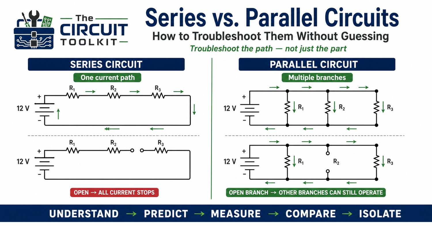
Series and parallel circuits are usually introduced during the first few lessons in electronics. The formulas are straightforward, so it is easy to treat the subject as something you learn once and leave behind.
At the troubleshooting bench, however, the distinction becomes extremely important.
An open component in a series circuit can stop current through the entire path. An open branch in a parallel circuit may disable only that branch while everything else continues operating.
Understanding the circuit topology therefore helps you predict the symptoms before you take your first measurement.
What makes a circuit series?
Components are in series when they share a single current path.
Because there is only one path, the same current flows through every series component:
I₁ = I₂ = I₃ = ITotal
The supply voltage is divided among the components:
VTotal = V₁ + V₂ + V₃
And series resistances add:
RTotal = R₁ + R₂ + R₃
Consider three 1 kΩ resistors connected in series across 12 V.
The total resistance is:
3 kΩ
Using Ohm's Law:
I = 12 V / 3,000 Ω = 4 mA
Because the resistors are equal, each resistor drops approximately 4 V.
That gives us something extremely useful for troubleshooting: expected measurements.
What happens when a series circuit opens?
Imagine that the second resistor becomes open.
The current path is now broken.
Ideally:
Circuit current = 0 A
The remaining components do not continue carrying the original 4 mA because there is no complete path back to the source.
This creates a useful diagnostic pattern. Depending on where you place the meter reference, you may find supply potential on one side of the open and a very different potential on the other.
Instead of replacing every component, you can follow the expected voltage path until normal behavior disappears.
What makes a circuit parallel?
Parallel branches are connected across the same two nodes.
That means each branch sees the same voltage:
V₁ = V₂ = V₃ = VSupply
But the current can be different in each branch.
Total current is:
ITotal = I₁ + I₂ + I₃
Suppose three 1 kΩ resistors are connected in parallel across 12 V.
Each branch sees 12 V and therefore draws:
12 V / 1,000 Ω = 12 mA
The supply delivers approximately:
36 mA total
Now the troubleshooting behavior is completely different.
If one branch opens, the other two can continue operating. Total current falls to approximately 24 mA, but the remaining healthy branches still have 12 V across them.
That symptom immediately tells us something about the circuit architecture.
Use symptoms to narrow the search
Suppose an electronic system contains three indicator circuits.
If all three stop operating simultaneously, look for something they share:
- Common supply
- Ground or return path
- Fuse
- Connector
- Enable signal
- Upstream protection device
If only one stops operating, investigate that individual branch first.
This principle scales far beyond simple resistor circuits.
Professional equipment often contains dozens of functional branches sharing common power rails and returns. Thinking in terms of shared versus individual paths can dramatically reduce troubleshooting time.
What about a short circuit?
An open interrupts a current path. A short creates an unintended low-resistance path.
In a parallel system, a shorted branch can draw excessive current while the other branches are still electrically connected to the supply.
Depending on the source and protection system, that may:
- Blow a fuse
- Trip current limiting
- Pull down the supply voltage
- Overheat wiring or components
- Shut down the entire system
So a fault in one parallel branch can sometimes appear to be a system-wide problem.
This is why understanding the protection circuitry matters.
Voltage measurements tell a story
One of the most effective troubleshooting habits is to stop thinking of voltage measurements as isolated numbers.
Instead ask:
Where should the voltage be?
Where should voltage drop occur?
Which components share the same nodes?
What changes if this path opens?
For a series path, individual voltage drops should add approximately to the applied voltage, consistent with Kirchhoff's Voltage Law.
For parallel branches, the voltage across each branch should be approximately the same when measured across the same two nodes.
When measurements violate those expectations, you have a clue.
Resistance measurements require caution
A resistance measurement across a component that remains connected to a parallel network may not represent that component's resistance alone.
The meter can see other paths through the circuit.
That is why a resistor that should measure 10 kΩ might appear substantially lower when tested in-circuit.
Before declaring it defective, study the schematic and determine whether another current path exists.
Resistance and continuity testing should also be performed with the circuit de-energized and stored energy safely discharged.
Develop a topology-first troubleshooting method
Before touching the probes to a circuit, identify:
What is in series?
What is in parallel?
Which nodes are shared?
Which supply and return paths are common?
Then predict what you should measure.
A useful workflow is:
Understand → Predict → Measure → Compare → Isolate
This is much more efficient than randomly checking components.
The more quickly you recognize circuit topology, the faster you can convert a symptom into a logical troubleshooting path.
Your current Beginner’s Guide to Circuit Troubleshooting and Design is specifically aimed at building these practical fundamentals for troubleshooting, repair, and circuit understanding.
Explore The Circuit Toolkit guides
Safety: De-energize equipment and safely discharge stored energy before resistance or continuity testing. Live voltage measurements require properly rated test equipment and procedures appropriate to the circuit's voltage and available energy.