

If there is one circuit that appears in almost every area of electronics—from Arduino projects to industrial control systems—it is the voltage divider.
Understanding how it works is one of the biggest milestones for students learning electronics because it connects several core concepts:
- Ohm's Law
- Series circuits
- Kirchhoff's Voltage Law
- Sensor interfaces
- Analog measurements
Once you understand voltage dividers, many circuits that once looked complicated suddenly become much easier to analyze.
What Is a Voltage Divider?
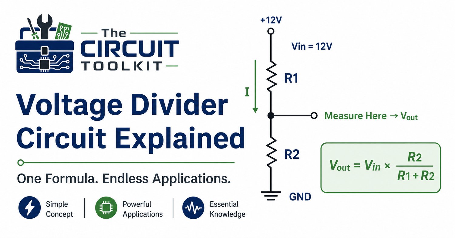
A voltage divider is simply two resistors connected in series across a voltage source.
Instead of taking the output across the entire source, you measure the voltage across one of the resistors.
That smaller voltage becomes your output.
Voltage dividers are used to:
- Create reference voltages
- Bias transistors
- Interface sensors
- Reduce voltages for analog inputs
- Measure battery voltage safely
- Generate comparator thresholds
They're everywhere because they're simple, inexpensive, and predictable.
The Formula
The voltage divider equation is one of the most useful formulas in electronics:
Vout = Vin × (R₂ / (R₁ + R₂))
Where:
- Vin = supply voltage
- R₁ = upper resistor
- R₂ = lower resistor
- Vout = voltage measured between the resistors and ground
The important detail is where you measure.
The output is taken from the junction of the two resistors, referenced to the circuit ground.
Example
Suppose you have:
- Vin = 12 V
- R₁ = 3 kΩ
- R₂ = 3 kΩ
Since both resistors are equal, each drops half the supply voltage.
Vout = 6 V
This simple example demonstrates why equal-value resistors create a 50% voltage division.
Why Voltage Dividers Sometimes "Stop Working"
One of the biggest surprises for beginners is that the voltage divider equation assumes the output is not heavily loaded.
If a circuit connected to Vout draws significant current, the effective resistance changes and the output voltage drops below the calculated value.
This is called loading.
Good design practices include:
- Making the divider current significantly larger than the load current when appropriate.
- Buffering the divider with an operational amplifier or other suitable stage if the load must be isolated.
- Checking the input impedance of the device receiving the divided voltage.
Ignoring loading is one of the most common causes of incorrect measurements in sensor circuits.
Common Troubleshooting Mistakes
When a measured divider voltage doesn't match the calculation, don't assume the resistors are bad.
Check these first:
- Incorrect resistor values
- Wrong resistor locations
- Poor ground connection
- Incorrect meter reference point
- Excessive load connected to the divider
- Open solder joint
- Damaged PCB trace
Many troubleshooting sessions end quickly once the measurement reference and resistor values are verified.
Where You'll Find Voltage Dividers
Voltage dividers appear in countless electronic systems.
Examples include:
- Potentiometers
- Temperature sensors
- Battery monitors
- Light sensors
- Audio controls
- ADC inputs
- Comparator circuits
- Transistor bias networks
If you begin recognizing voltage dividers inside schematics, you'll start understanding larger circuits much faster.
Practical Technician Tip
Whenever you're troubleshooting a voltage divider:
- Measure the supply voltage.
- Measure across R₁.
- Measure across R₂.
- Verify the resistor values with power removed and stored energy safely discharged.
- Compare the measured voltages to the expected calculations.
Taking three voltage measurements often tells you more than replacing three components.
Build Strong Fundamentals
Many technicians spend years repairing equipment without fully understanding why a voltage divider behaves the way it does.
Once you master this simple circuit, transistor bias networks, analog sensors, reference voltages, and many power supply circuits become much easier to understand.
If you're building a stronger electronics foundation, the Electronics Fundamentals guide from The Circuit Toolkit covers voltage dividers, Ohm's Law, Kirchhoff's Laws, Thévenin's theorem, diodes, transistors, and practical circuit analysis in a structured format designed for students, hobbyists, and technicians.
Safety Reminder
Always de-energize equipment and discharge stored energy before measuring resistance or continuity. When making live voltage measurements, follow appropriate safety procedures, use correctly rated instruments, and avoid contact with exposed energized conductors.