

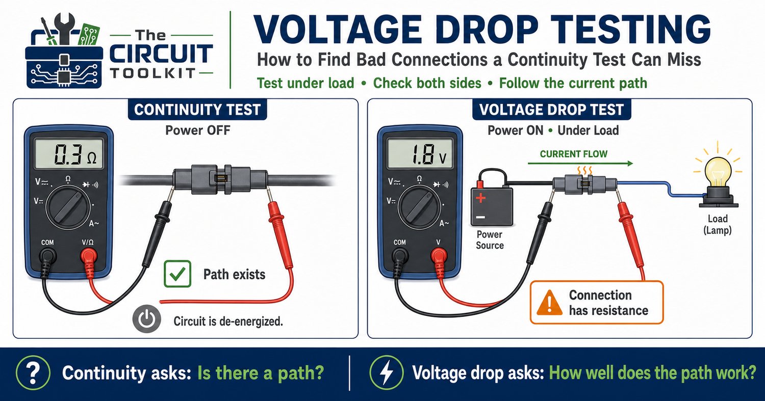
A circuit stops working correctly, so you turn off the power, grab your multimeter, and check continuity through the wiring.
Beep.
The connection looks good.
You power the circuit again—and the problem is still there.
This is a common troubleshooting trap. A continuity test can tell you that an electrical path exists, but it does not necessarily prove that the path can carry the required operating current without excessive voltage loss.
That's where voltage-drop testing becomes valuable.
Continuity doesn't always mean a good connection
Most digital multimeters perform continuity testing using a very small test current.
A damaged wire, oxidized connector, worn switch contact, cracked solder joint, or partially broken conductor may still provide enough electrical connection for the meter to indicate continuity.
Under actual operating load, however, that same connection may develop a significant voltage drop.
Imagine a connector that has developed 2 Ω of unwanted resistance.
A continuity test may still recognize it as a conductive path.
Now operate a load that draws 1 A.
Using Ohm's Law:
V = I × R
V = 1 A × 2 Ω = 2 V
You've just lost 2 V across something that should ideally have very little voltage across it.
In a 12 V circuit, the load may now receive only about 10 V.
Measure across the connection
Voltage-drop testing is different from measuring supply voltage.
Instead of measuring from the supply to ground, place the meter probes across the component or connection you suspect while the circuit is operating under its normal load, provided live testing is safe and appropriate.
Consider a cable connecting a 12 V supply to a load.
If you place one probe on the supply side of the cable and the other on the load side, you're measuring the voltage lost along that section of the current path.
An ideal conductor would have zero resistance and therefore zero voltage drop.
Real conductors always have some resistance, so some drop is normal. The acceptable amount depends on conductor length, current, connector specifications, circuit requirements, and the manufacturer's design limits.
The important question is:
Is the measured drop reasonable for this part of the circuit?
Test both sides of the circuit
Don't investigate only the positive supply path.
The return or ground path is equally important.
Suppose a load receives 12 V on its positive terminal, but the ground connection has developed significant resistance.
The load may still malfunction because the current cannot return efficiently to the source.
This is why a technician should think in terms of a complete current loop:
Source → Wiring → Switch/Connector → Load → Return → Source
Any unwanted resistance in that loop can create voltage loss.
Why grounds create confusing symptoms
A poor common ground can produce especially strange behavior because multiple circuits may share the same return path.
Symptoms can include:
- Unstable sensor readings
- Dim indicators
- Intermittent operation
- Unexpected resets
- Relays that chatter
- Different voltages depending on which reference point you use
If several apparently unrelated circuits malfunction simultaneously, investigate what they share.
A common supply is one possibility.
A common return is another.
Compare measurements under load
A power supply reading 12 V with nothing connected does not prove that the system receives 12 V during operation.
Likewise, a connector measuring correctly when no meaningful current is flowing may fail once the load is activated.
This gives us an important troubleshooting principle:
Test the circuit under the conditions that produce the fault.
Suppose a motor controller works until the motor starts.
Measure the supply at the controller while the motor is running.
If the supply collapses, work backward through the power path.
Measure across:
- Connectors
- Fuse holders
- Switches
- Relays
- Cable sections
- Ground connections
A significant voltage appearing across a connection that should have very little drop points toward unwanted resistance.
Voltage drop can also reveal heat
Power dissipated in an unwanted resistance is:
P = I²R
Return to our 2 Ω connection carrying 1 A:
P = 1² × 2 = 2 W
That means the bad connection is dissipating 2 W as heat.
Increase the current to 3 A and the situation becomes dramatically worse:
P = 3² × 2 = 18 W
This is why high-resistance connections can become hot, discolor connectors, damage insulation, and eventually fail completely.
The fault may begin as intermittent behavior and eventually become a burned connection.
A practical troubleshooting sequence
When you suspect a wiring or connection problem:
1. Inspect. Look for corrosion, loose terminals, damaged wires, overheated connectors, or cracked solder joints.
2. Verify source voltage. Confirm that the supply itself is operating correctly.
3. Operate the load. Reproduce the fault when safe to do so.
4. Measure across suspect connections. Look for unexpected voltage loss.
5. Check the return path. Don't assume ground is perfect.
6. Compare with specifications. Determine whether the measured drop is acceptable for that circuit.
7. Repair the cause. Clean, tighten, replace, or repair the defective connection as appropriate.
Then retest under load.
Add voltage-drop testing to your toolkit
A continuity test answers:
"Is there an electrical path?"
A voltage-drop test can answer:
"How well does that path work while carrying current?"
Understanding the difference can prevent hours of unnecessary component replacement.
The current Circuit Toolkit store includes the Beginner Circuit Troubleshooting Guide PDF | Step-by-Step Electronics Repair Checklist, designed around developing this kind of systematic troubleshooting process rather than guessing which component to replace.
Safety: Voltage-drop testing is normally performed on an energized circuit. Only perform live measurements when you are trained for the equipment involved and can do so safely. Use correctly rated instruments and probes, keep hands away from exposed energized conductors, and follow appropriate electrical-safety procedures. Do not use this technique on hazardous-energy circuits without the required training and controls.