

One of the biggest differences between a beginner and an experienced electronics troubleshooter isn't the quality of their multimeter—it's the way they collect information.
Beginners often measure one point, replace a component, power the circuit again, and hope for the best.
Experienced technicians do something different.
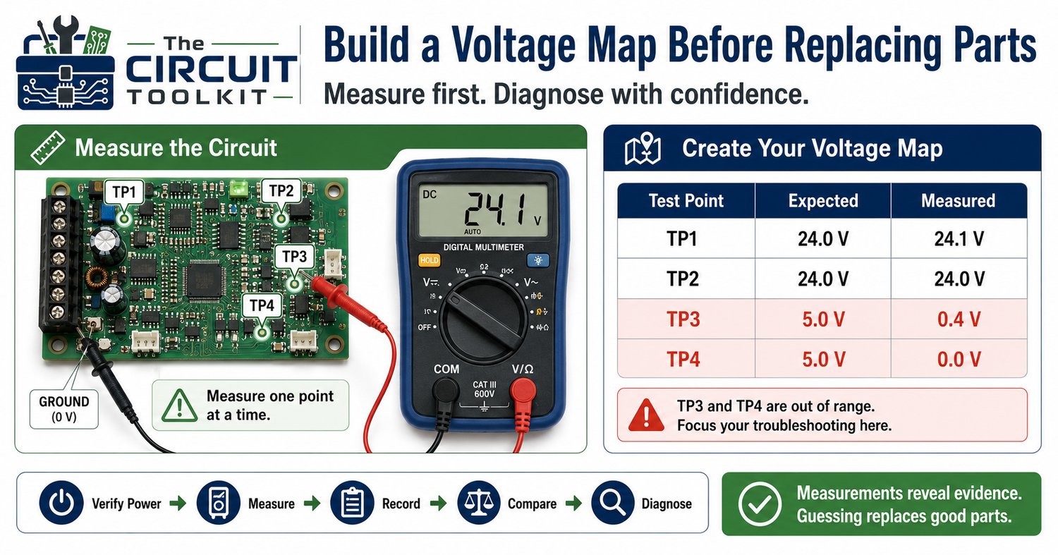
They build a voltage map.
Instead of relying on one measurement, they record voltages throughout the circuit and compare them with the expected operating values. This transforms troubleshooting from guessing into a logical investigation.
If you're trying to repair power supplies, control boards, or embedded electronics, learning to build a voltage map is one of the most valuable skills you can develop.
What Is a Voltage Map?
A voltage map is simply a record of voltage measurements taken at key locations throughout a circuit while it is operating under normal conditions.
Typical measurement points include:
- Power supply output
- Voltage regulator input
- Voltage regulator output
- Connector pins
- Microcontroller supply pins
- Relay coils
- Sensor outputs
- Ground reference points
When these readings are organized, patterns begin to emerge.
Instead of asking "What part should I replace?", you begin asking:
"Where does the voltage stop behaving normally?"
That's usually where the real problem begins.
Start at the Power Source
Every troubleshooting session should begin by verifying that the circuit is receiving the correct supply voltage.
For example:
- 24 V industrial controller
- 12 V automotive module
- 5 V logic supply
- 3.3 V microcontroller rail
If the primary supply is incorrect, every measurement downstream becomes unreliable.
Always verify the source before chasing symptoms.
Follow the Electrical Path
Electric current follows a path from the source to the load and back again.
Measure along that path one point at a time.
For example:
- Power supply
- Fuse
- Connector
- Switch
- Relay
- Load
- Return path
The first unexpected voltage reading often identifies the section containing the fault.
This approach is much faster than checking components randomly.
Compare Input and Output
Many electronic components are designed to change voltage.
Examples include:
- Voltage regulators
- DC-DC converters
- Operational amplifiers
- Transistor switches
Whenever possible, measure both the input and output.
Suppose a voltage regulator has:
- Input: 12.1 V
- Expected output: 5.0 V
- Measured output: 0.3 V
Now you know the supply reaches the regulator, but the regulated output is incorrect.
That narrows the problem considerably.
Don't Forget Ground
Voltage is always measured relative to a reference point.
A poor ground connection can create misleading voltage readings.
Whenever measurements seem inconsistent:
- Verify the ground connection.
- Measure the voltage drop across ground conductors.
- Check connectors and return paths.
A damaged ground can make healthy components appear faulty.
Record Your Measurements
One of the simplest habits that separates professional technicians from beginners is writing measurements down.
Instead of relying on memory, create a table like this:
Test PointExpectedMeasuredPower Supply24.0 V24.1 VFuse Output24.0 V24.1 VRegulator Input24.0 V24.0 VRegulator Output5.0 V0.4 V
A voltage map quickly highlights where normal operation ends.
Avoid a Common Mistake
Many people stop troubleshooting as soon as they find an abnormal voltage.
Instead, ask another question:
Why is the voltage incorrect?
For example:
A low voltage could result from:
- A failed regulator
- A shorted downstream load
- Excessive voltage drop
- Loose connector
- Blown fuse
- Damaged PCB trace
The abnormal voltage is a clue—not necessarily the failed component.
Use Voltage Mapping with Other Measurements
Voltage mapping becomes even more powerful when combined with:
- Resistance measurements (power removed)
- Continuity testing
- Current measurements
- Voltage-drop testing
- Visual inspection
Each measurement answers a different question.
Together, they reveal the complete electrical story.
Safety Always Comes First
Voltage mapping requires energized equipment.
Before taking measurements:
- Wear appropriate PPE when required.
- Use insulated probes in good condition.
- Select the correct meter range before probing.
- Keep fingers behind probe guards.
- Avoid slipping between adjacent conductors.
- Never change meter functions while the probes are connected to hazardous voltage.
Working methodically is safer than rushing from point to point.
Conclusion
A voltage map isn't complicated—it simply organizes information.
Instead of replacing components based on suspicion, you collect evidence one measurement at a time until the fault becomes obvious.
That's how experienced troubleshooters diagnose circuits efficiently.
The more complete your voltage map, the less likely you are to replace good parts.
Measure first.
Replace second.
If you're learning circuit diagnostics, the Beginner Circuit Troubleshooting Guide from The Circuit Toolkit provides a structured troubleshooting workflow that pairs perfectly with voltage mapping. It shows where to measure, how to interpret readings, and when to switch between voltage, resistance, continuity, and current measurements so you can diagnose faults confidently instead of guessing.