

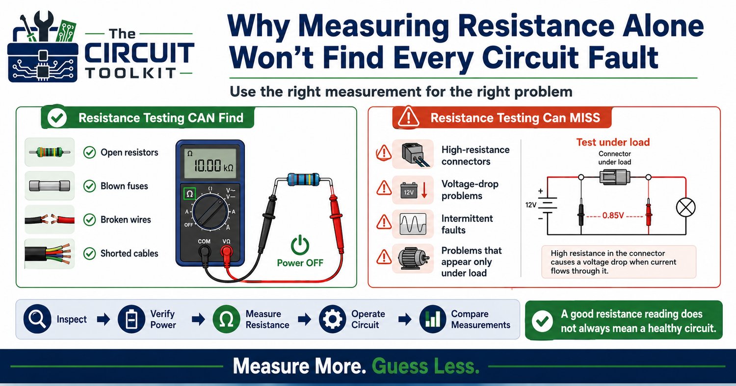
One of the first things most technicians learn is how to measure resistance.
It's simple.
Turn off the circuit, switch the multimeter to Ω, touch the probes, and compare the reading to the expected value.
Resistance measurements are extremely valuable—but they're also one of the most misunderstood tools in electronics troubleshooting.
A resistance measurement tells you about a circuit without normal operating current flowing. Many failures only reveal themselves when current is actually moving through the circuit.
Understanding what resistance measurements can—and cannot—tell you will make your troubleshooting faster, more accurate, and far less frustrating.
What Resistance Measurements Are Good At
When power has been safely removed and stored energy has been discharged, resistance testing is excellent for finding:
- Open resistors
- Blown fuses
- Broken wires
- Open PCB traces
- Shorted cables
- Damaged switches
- Open transformer windings
- Failed heating elements
These are static faults.
The circuit isn't operating, but the component's electrical condition can still be evaluated.
For example, if a 1 kΩ resistor measures 998 Ω, it's probably healthy.
If it measures 15 MΩ or OL (open loop), you've likely found your problem.
Where Resistance Measurements Can Mislead You
Suppose a connector has become slightly corroded.
Instead of adding only a few milliohms of resistance, it has developed several ohms of unwanted resistance.
When your multimeter performs a resistance measurement, it injects only a tiny test current.
That small current may pass through the corrosion without difficulty, making the connector appear perfectly acceptable.
Later, when the circuit draws two or three amps, that same connection develops a significant voltage drop, generates heat, and the equipment begins to fail.
Nothing about the resistance test warned you.
Parallel Components Can Fool Your Meter
Another common mistake is forgetting that components remain connected together.
Imagine measuring a resistor that's still soldered onto a circuit board.
The resistor itself may be 10 kΩ.
However, another 10 kΩ resistor connected in parallel produces an effective resistance of approximately 5 kΩ.
The meter isn't lying.
It's simply measuring every available current path.
Whenever a resistance reading doesn't make sense, ask yourself:
"Am I measuring the component, or the entire circuit around it?"
Sometimes one lead must be lifted from the board before an accurate measurement can be made.
Resistance Doesn't Measure Performance
A relay coil can measure exactly the correct resistance.
The relay may still fail to pull in because:
- The supply voltage collapses under load.
- The driver transistor cannot supply enough current.
- A connector develops excessive voltage drop.
- The power supply current limit activates.
- A control signal never reaches the relay.
Every one of these faults could exist while the relay coil resistance measures perfectly.
This is why experienced technicians rarely rely on one measurement.
The Best Troubleshooting Method
Instead of asking only one question, ask several.
Does the correct voltage reach the component?
Is the expected current flowing?
Is resistance normal?
Is continuity present?
Is there excessive voltage drop anywhere in the path?
Each measurement tells a different part of the story.
Together they reveal the complete picture.
Build a Logical Measurement Sequence
A systematic workflow often looks like this:
1. Visual Inspection
Look for:
- Burned components
- Cracked solder joints
- Loose connectors
- Corrosion
- Broken wires
Many faults are visible before a meter ever comes out.
2. Verify Power
Measure supply voltage.
If the circuit never receives power, resistance measurements won't explain why.
3. Check Resistance (Power Removed)
Now evaluate:
- Fuses
- Resistors
- Windings
- Cables
- Switches
These measurements help eliminate obvious failures.
4. Operate the Circuit
If the fault only occurs while running, reproduce it safely.
Many intermittent problems only appear during normal operation.
5. Compare Measurements
Instead of trusting one reading, compare measurements at several points.
Where does the voltage change unexpectedly?
Where does current stop flowing?
Where does the signal disappear?
Those comparisons lead you directly toward the fault.
Think Like Current
One of the best habits any troubleshooter can develop is thinking like electric current.
Current must leave the source.
Travel through every connection.
Pass through the load.
Return to the source.
Anything that interrupts or restricts that journey creates symptoms.
Your job isn't simply to measure resistance.
Your job is to discover where the electrical path stops behaving the way it should.
Conclusion
Resistance measurements remain one of the most valuable diagnostic tools in electronics—but only when they're used appropriately.
They identify many static faults quickly, yet they cannot reveal every problem.
Professional troubleshooting comes from combining resistance, voltage, current, continuity, and voltage-drop measurements into one logical diagnostic process.
The more measurements you compare, the less guessing you do.
If you're learning electronics troubleshooting, the Beginner Circuit Troubleshooting Guide PDF | Step-by-Step Electronics Repair Checklist in The Circuit Toolkit walks through a practical diagnostic workflow that helps you decide which measurement to make first, what it means, and where to go next. It pairs perfectly with the store's multimeter and Ohm's Law reference guides to help you troubleshoot with confidence rather than guesswork.