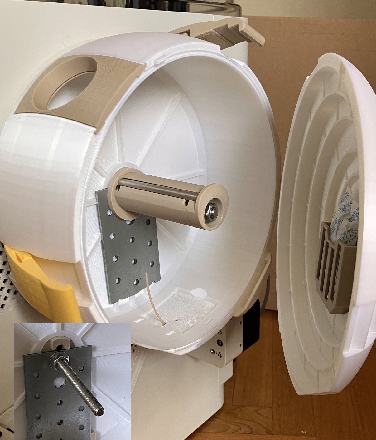
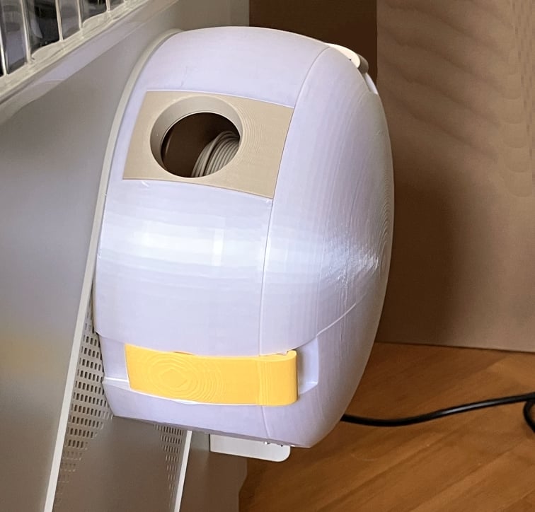
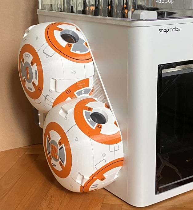
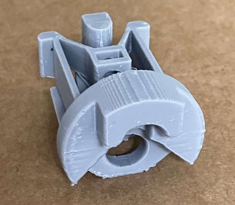
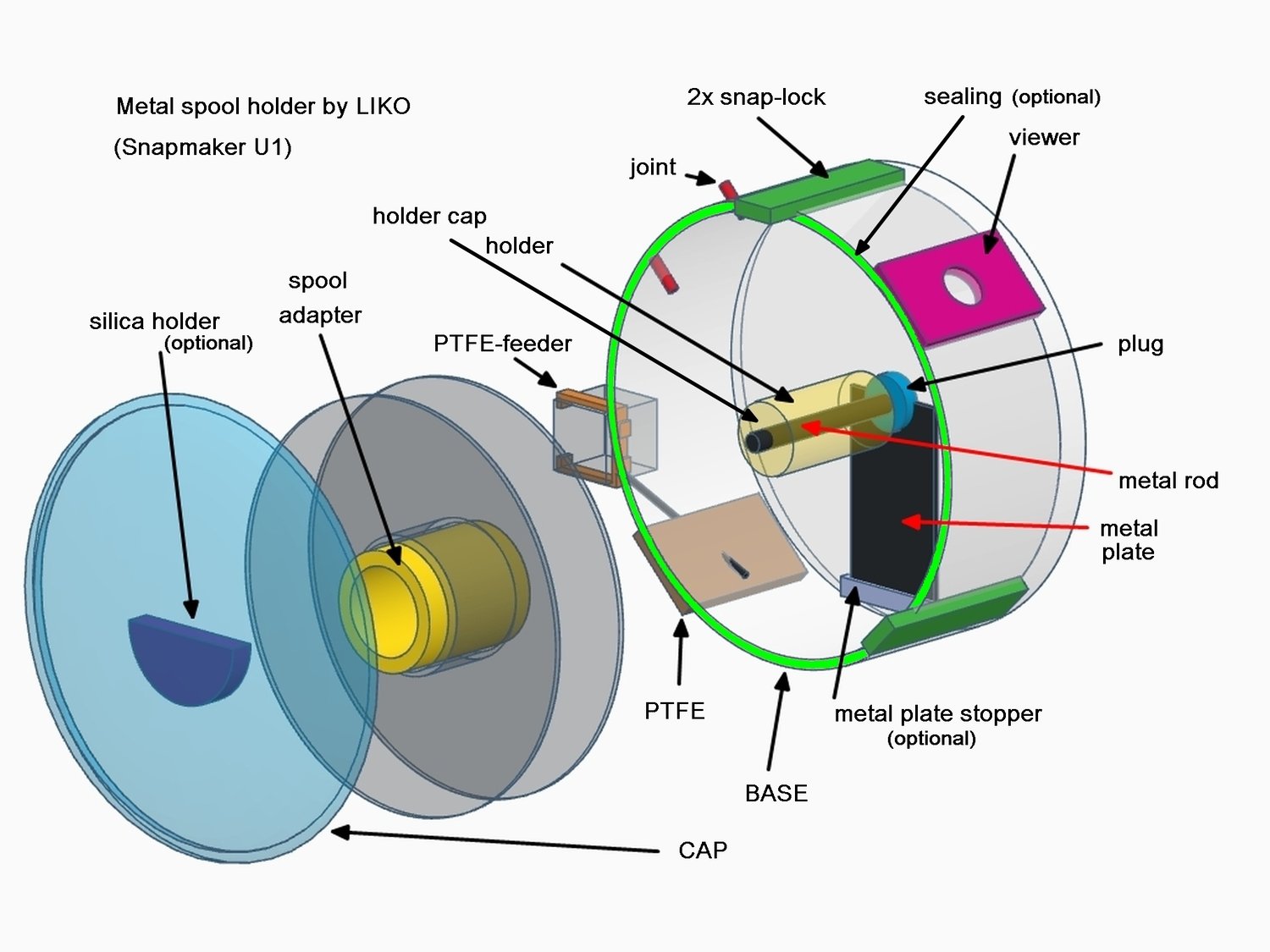
You will need to print out 16 files: 1 file is the PTFE adapter (free) and 15 files from the ZIP (paid).
>>> 1 file: PTFE adapter <<<
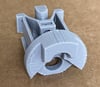
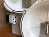
This adapter goes on the U1 filament feeder cube to hold the 'other end' of the PTFE tube. There are different dimensions of ECAS04 fittings. You can print my version of adapter, or what KEN830 designed (details and link at Legal section below) or anything else.
>>> 15 files: the ZIP <<<
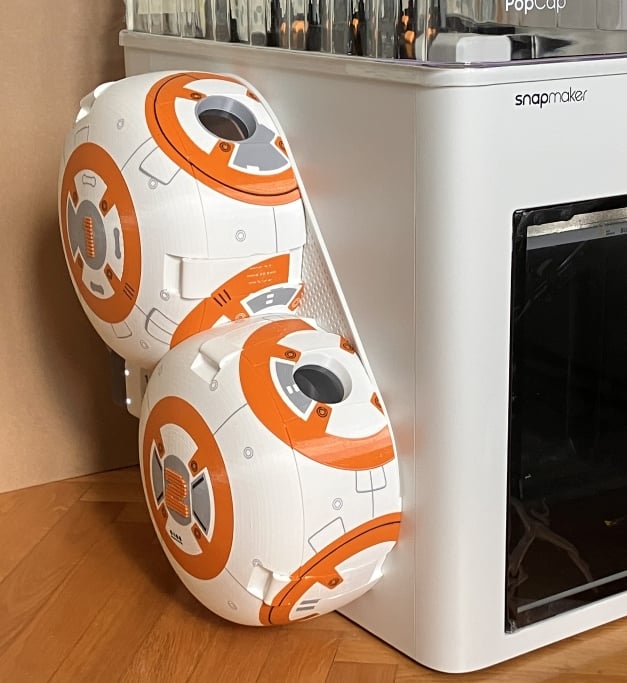
You need to print each files only once: 8 for the 4x CAP-BASE pairs and 7 for the other parts. Actually, there are 19 files in the ZIP because there are 2 sets of the 4 BASE files, depending on the sealing solution you prefer.
The file naming in the ZIP I used for the holders is: LU-LeftUpper, LL-LeftLower, RU-RightUpper, RL-RightLower, viewing from the front.
GENERAL SETTINGS
1. I hope you did Dynamic Flow Calibration at least once, when you installed your printer. Pls do now, if you didn't.
2. Please set/do Heated Bed Leveling before printing each 15 files.
3. You should check and set your filament profile parameters to the filament you use, before you print.
4. Print settings: I used for all files the default Snapmaker settings (for both PLA and PETG parts), they are good and I had to defer only a few things, I listed them below. The major default settings were:
- 0,4 nozzle, 0,2 layer height
- 2 wall, 3 bottom, 5 top layers, 15% infill
- default speed, no support.
- most of my filaments were high speed, they print fine.
INDIVIDUAL SETTINGS FOR PARTS
These are the specific settings in the 15 files below. They are all set in the .3MF files, but make sure they are there. Also, please check the Objects/Plate in the Preview mode, to be sure these settings took effect (maybe different future Orca slicer SW will work differently).
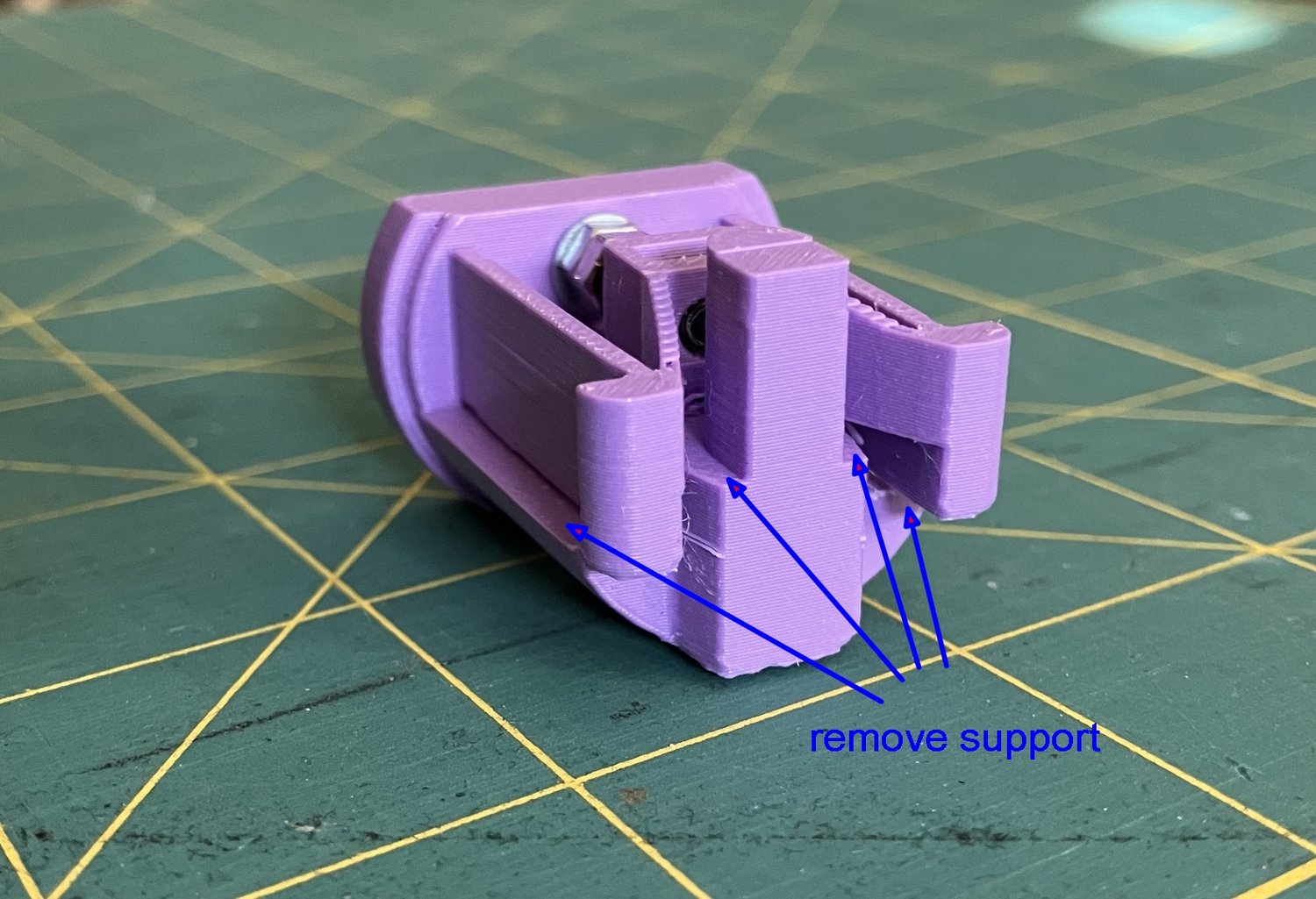
1-PLUG: Support: YES. Wall: 3 layers. First layer: 0.22
2-HOLDER: Support: YES. Bridge.speed: 30 mm/s.
3-ADAPTER: Brim: only outter.
4-MISC: none.
5-SNAP: Support: YES (not 'Tree' but 'Normal', 'Grid', 90 degree). Variable layer height: YES (the top should be finer). Wall: 3 layers, bottom: 5 layers. Bridge.speed :30 mm/s. No brim.
6-VIEWER: No brim. Variable layer height: optional (you may want to set the top finer).
7-PTFE: No brim. Variable layer height: optional (you may want to set the top finer).
8-11 (x2)-BASE: Support: YES (default 'Tree auto'). Brim: YES.
12-15-CAP: Support: NO (file includes the scaffolding I designed, it saves ~8 hrs print time on each CAP). Varable layer height: YES (we all want the top part look finer than .2). Bridge.speed: 30 mm/s. Brim: Outter only, 5mm.
COMMENTS FOR PARTS PRINTING:
- PLUG: The plug is sensitive since its in(!) the printer house and therefore it could warm up when the air in the U1 is warm. You will need a temperature resistant but also flexible (plug has a rarely 'moving' part) material: its not PLA, it should be at least PETG or ASA/ABS.
- ADAPTER: when you print the ADAPTER, dont flip back any of the parts upside down. I know they look weird on the plate, but the thread will work much better this way.
- BASE: There are 2 sets (2x4) files for the base. The print settings are the same, the only difference is the groove dimension for the sealing: the 'tube' is for OD 2,5mm silicon tube, while the 'TPU' intended for 1,75mm TPU filament as sealing (pls note, I could not test the groove for the TPU version, but I think the 1,5x1,5mm groove should be good). Print the version according to your sealing solution.
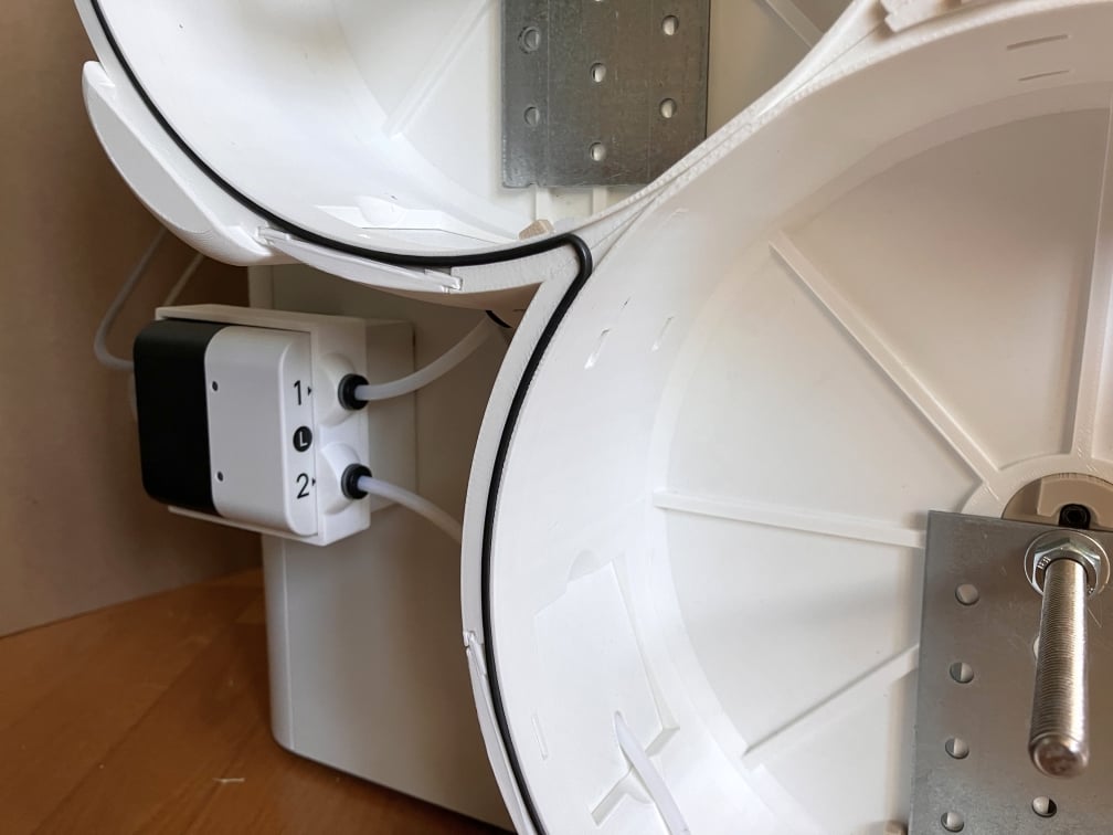
- BASE: the importance of the support is two-fold: first, to have a proper shape at the bottom: there is a circular groove along the edge and it must look nice to fit on the U1 side cover. Second, there is a hump on the top of the base (guides the cap), make sure it has supports too. However, if the Orca does not slice a support for the top of the 2x 'windows' (1-1 for the VIEWER and PTFE modules), its not a problem: the bridge will be fine.
- CAP: dont increase the bridge speed (keep 30 mm/s or even less), otherwise the inside of the CAP will look not nice.